Pickup device having a heat-radiation path

a pick-up device and heat-radiation path technology, which is applied in the direction of disposing/mounting heads, instruments, data recording, etc., can solve the problems of deterioration easy accumulation of laser light sources, so as to prevent the increase of the temperature of light sources and reduce manufacturing costs.

Inactive Publication Date: 2006-10-17
PIONEER CORP
View PDF9 Cites 10 Cited by
  • Summary
  • Abstract
  • Description
  • Claims
  • Application Information

AI Technical Summary

Benefits of technology

[0011]An object of the present invention is to provide a pickup device capable of preventing increase in temperature of a light source, at low manufacturing costs.

Problems solved by technology

When the laser light source and the grating are thus respectively provided at one end and another end of the communication hole, however, the heat generated from the laser light source easily accumulates in the communication hole, so that the temperature of the laser light source increases.
As the temperature of the laser light source increases, a problem arises in that the characteristics of the laser light source deteriorate or the lifetime thereof is shortened.
The amount of heat generated from these laser light sources is so large that the heat-radiating plate is not enough to achieve sufficient heat radiation for these laser light sources.

Method used


Image

  • Pickup device having a heat-radiation path
  • Pickup device having a heat-radiation path
  • Pickup device having a heat-radiation path

Examples


first embodiment

(First Embodiment)

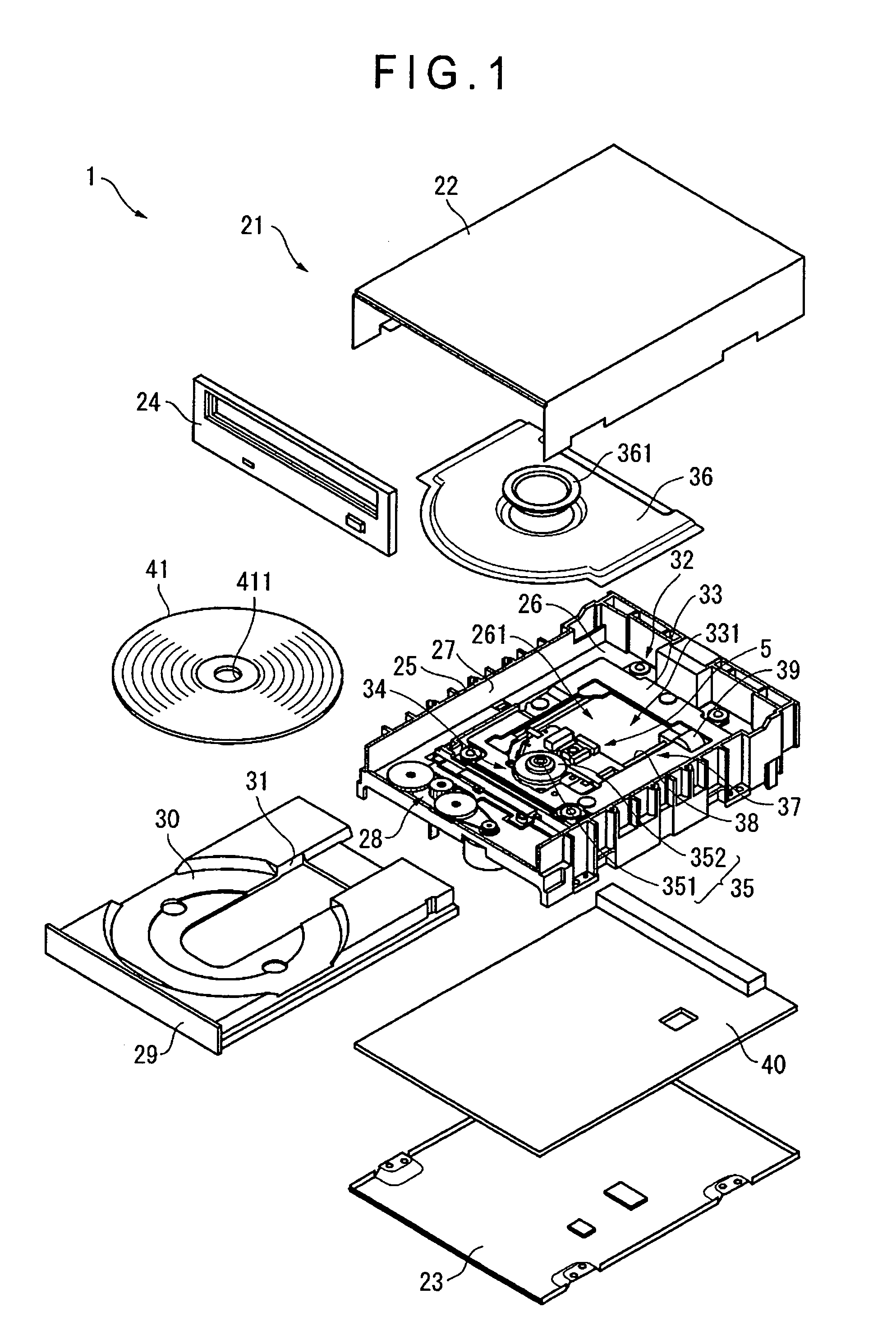
[0024]FIG. 1 is an exploded perspective view of a disk apparatus which has a pickup device according to a first embodiment and reproduces data recorded on an optical disk such as a DVD or a CD or records data onto the optical disk.

[0025]A disk apparatus 1 includes an outer case 21, an inner case 25 provided inside the outer case 21, a disk tray 29 which is provided to be advanceable and retractable relative to the inner case 25 and on which an optical disk 41 is set as an optical recording medium, a main unit 32 which is provided in the inner case 25 and reproduces or records data from or onto the optical disk 41, and a circuit board 40 including an electronic component which controls the operation of the main unit 32.

[0026]The outer case 21 includes an upper case 22 whose bottom and front sides are open as shown in FIG. 1, a lower case 23 which closes the bottom side of the upper case 22, and a decorative panel 24 which closes the front side of the upper case 22. ...

third embodiment

(Third Embodiment)

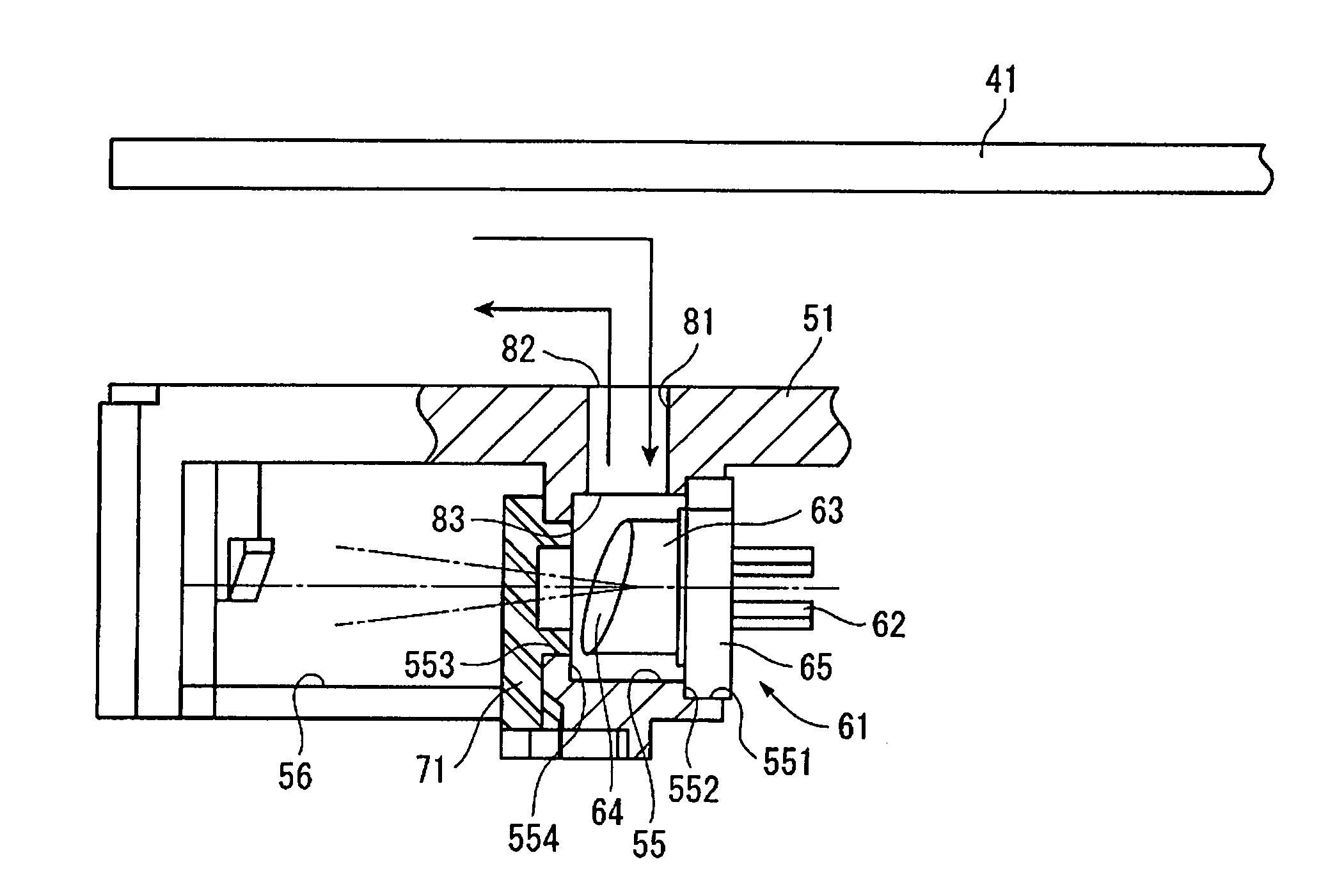
[0076]FIG. 5 shows a third embodiment of the present invention. The basic structure of the third embodiment is the same as the first embodiment. The third embodiment, however, differs from the first embodiment in that the heat radiation path 81 as a heat radiator is provided with an air flow receiver 84.

[0077]That is, the air flow receiver 84 having a wall facing the flow of the air generated by rotation of the optical disk 41 is provided at an edge of the outer opening 82 of the heat radiation path 81.

[0078]The wall opposed to the air flow is flat and parallel to the axis of the heat radiation path 81.

[0079]The air flow receiver 84 is formed so as to stand integrally on the pickup base 51.

[0080]According to this structure, the following advantage can be achieved in addition to the advantages (1) to (7) of the foregoing embodiments.[0081](9) The air flow receiver 84 having the wall facing the flow of the air generated by rotation of the optical disk 41 is provided ...

fourth embodiment

(Fourth Embodiment)

[0084]FIG. 6 shows a fourth embodiment of the present invention. The basic structure of the fourth embodiment is the same as the first embodiment. The fourth embodiment, however, differs from the first embodiment in that a dust guard 85 is included as a dust-proof unit.

[0085]The dust guard 85 includes a dust guard roof 851, which is provided opposed to and at a predetermined distance from the outer opening 82 and having an area covering the opening area of the outer opening 82, and an air flow receiver surface 852 which receives the flow of the air generated by rotation of the optical disk 41.

[0086]The dust guard 85 may be formed to be integral with the pickup base 51. Alternatively, the dust guard 85 may be provided separately on the pickup base 51 according to the first embodiment.

[0087]According to this structure, the following advantages can be achieved in addition to the advantages (1) to (7) and (9) of the foregoing embodiments.[0088](10) The heat radiation ...


PUM

PropertyMeasurementUnit
angleaaaaaaaaaa
areaaaaaaaaaaa
distanceaaaaaaaaaa

Abstract

A communication hole (55) is provided in a pickup base (51). A laser light source (61) is provided at an end of the communication hole (55). A grating (71) is provided at another end of the communication hole (55). The communication hole (55) is provided with a heat radiation path (81) which connects the inside of the communication hole (55) with the outside of the pickup base (51). Heat generated from the laser light source (61) is radiated from the heat radiation path (81).

Description

BACKGROUND OF THE INVENTION[0001]1. Field of the Invention[0002]The present invention relates to a pickup device which, for example, writes or reads data into or from an optical recording medium.[0003]2. Description of Related Art[0004]There has been a known pickup device which writes or reads data into or from an optical recording medium, e.g., optical disks such as a DVD (Digital Versatile Disk), a CD (Compact Disk), and the like.[0005]The pickup device is constituted by including a laser light source as a light source which irradiates a light beam onto an optical disk, a grating as an optical element provided in the middle of an optical path extending toward the optical disk from the laser light source, and a pickup base on which the laser light source and the grating are mounted.[0006]The pickup base is provided with a communication hole. The communication hole has, at an end, a light source attachment for attaching the laser light source, and an optical element attachment for a...

Claims


Application Information

Patent Timeline
Patent Type & Authority Patents(United States)
IPC IPC(8): G11B7/08G11B5/40G11B7/12G11B7/121G11B33/14
CPCG11B7/12G11B7/121
Inventor MURATA, MASAYAMIZUUCHI, YUICHIKOYAMA, MASAYUKIHAYASHI, TAKEHIKOIWANO, TSUYOSHI
Owner PIONEER CORP
Why Eureka
Try Eureka