
Retrofit breaker adapter system and method

a technology of adapter system and retrofitting breaker, which is applied in the direction of snap-action arrangement, manufacturing tools, electrical apparatus construction details, etc., can solve the problems of high cost or impracticality of maintenance of switchgear, new products that have not maintained compatibility with existing switchgear, and the installation of switchgear power circuit breakers that are costly or impractical to maintain

Active Publication Date: 2006-10-24
ABB (SCHWEIZ) AG
View PDF4 Cites 21 Cited by
  • Summary
  • Abstract
  • Description
  • Claims
  • Application Information

AI Technical Summary

Benefits of technology

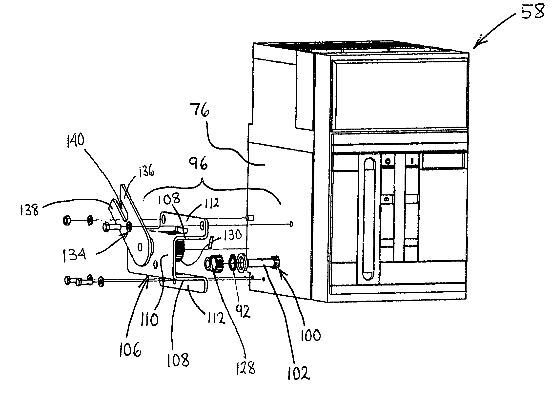
The present invention provides a method and assembly for retrofitting a circuit breaker into a switchgear assembly with a racking structure. The circuit breaker is not designed to mount in the cell and includes a mechanical linkage and gear assembly that is actuated by the shaft of the breaker. The gear assembly is mounted to the circuit breaker and operates to engage the racking structure of the cell, causing the breaker to move from a first, disconnected position to a second, connected position. The technical effect of this invention is to provide a simple and effective way to retrofit a circuit breaker into an existing switchgear assembly.

Problems solved by technology

Power circuit breakers from various manufacturers are not interchangeable, and as the manufacturers have eliminated older products and introduced new technologies, the new products have not maintained compatibility with existing switchgear.
The result is that many aging switchgear installations have power circuit breakers that are costly or impractical to maintain.
Complete replacement of switchgear is very expensive and requires significant downtime.
The current art for circuit breaker retrofits is time-consuming and costly, and may also impact customer system downtime for initial installation as well as on-going reliability issues.
This process requires additional space that complicates dielectric and heat run considerations, places an additional layer of interface that impacts reliability by creating additional points of failure for the racking system, increases susceptibility to high momentary currents, and increases material costs.
These processes complicate the interlocking and auxiliary contact functions, and require extensive custom design work and materials.

Method used


Image

  • Retrofit breaker adapter system and method
  • Retrofit breaker adapter system and method
  • Retrofit breaker adapter system and method

Examples


Embodiment Construction

[0020]It should be noted that in the detailed description that follows, identical components have the same reference numerals, regardless of whether they are shown in different embodiments of the present invention. It should also be noted that in order to clearly and concisely disclose the present invention, the drawings may not necessarily be to scale and certain features of the invention may be shown in somewhat schematic form.

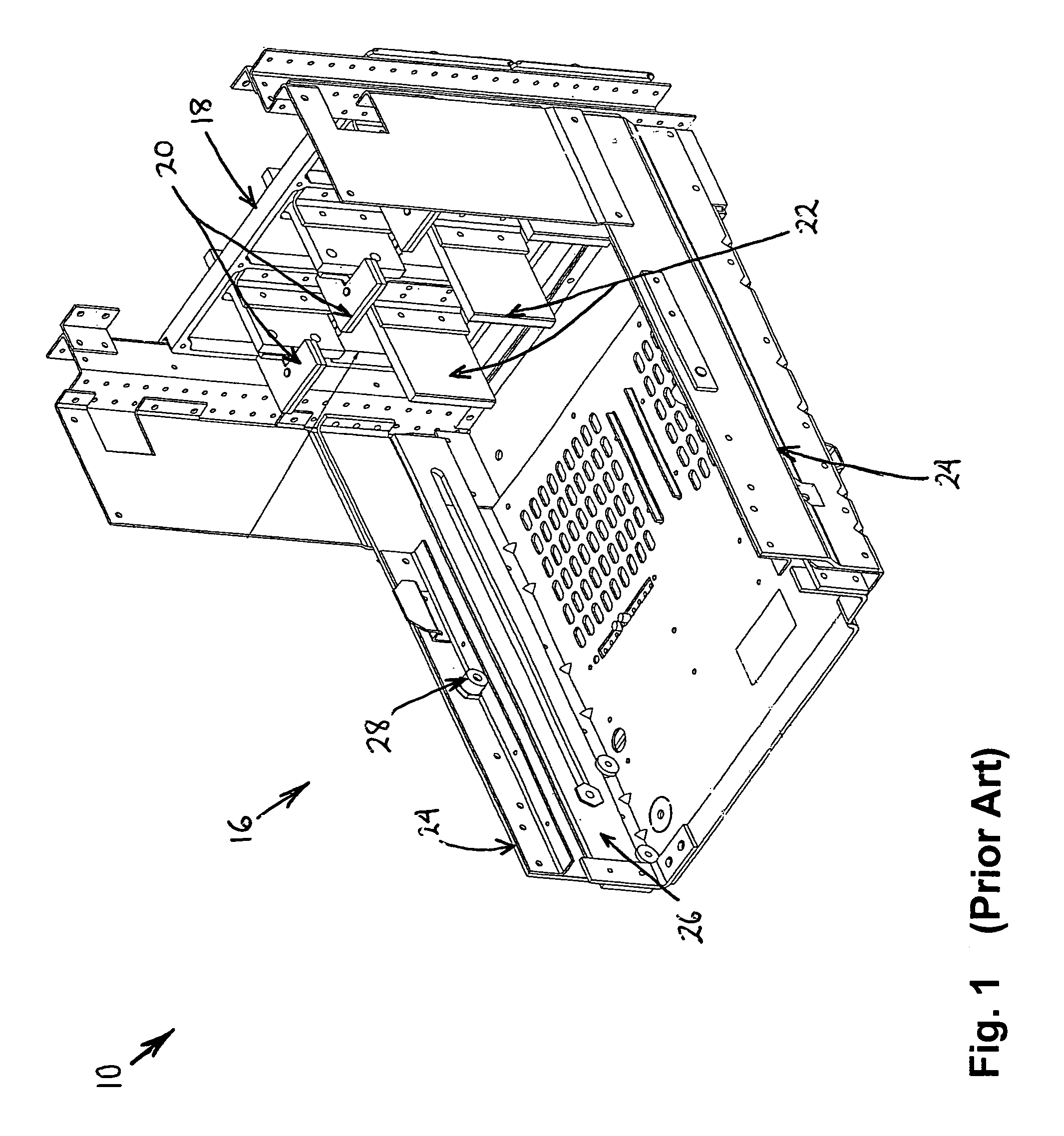
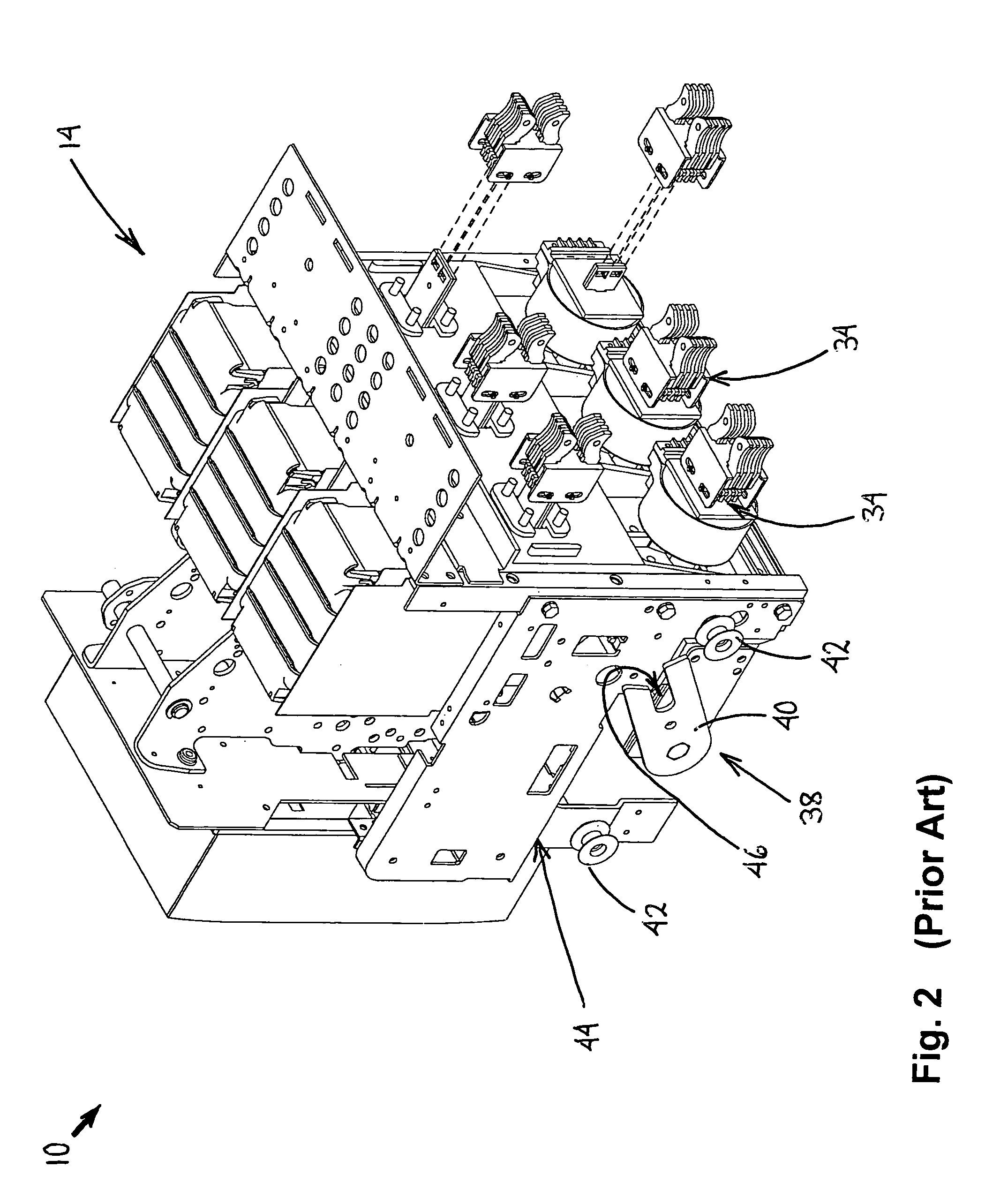
[0021]A prior art first switchgear system 10 with removable breakers is partially shown in FIGS. 1–3. The first switchgear system 10 includes a first cabinet 12 (shown in FIG. 11), a first circuit breaker 14 (shown in FIG. 2) and a first substructure 16 (shown in FIG. 11) for mounting in the first cabinet 12.

[0022]With particular reference to FIG. 1, the first substructure 16 includes a rear end wall 18 with upper and lower stabs 20, 22 extending inwardly therefrom and opposing side walls 24 having rails 26 movably mounted thereto. A pair of racking pins 28 ...


PUM

PropertyMeasurementUnit
rotationaaaaaaaaaa
voltageaaaaaaaaaa
shapeaaaaaaaaaa

Abstract

The present invention is directed to a system for modifying a circuit breaker for removable installation in a cell of switchgear system, wherein the unmodified circuit breaker is not adapted for mounting in the cell. The system includes an adapter frame to which the circuit breaker is mounted and gear assemblies mounted to opposing sides of the circuit breaker. The gear assemblies adapt a racking device of the circuit breaker so as to be operable to rack the circuit breaker within the cell of the switchgear system.

Description

CROSS-REFERENCE TO RELATED APPLICATIONS[0001]This application claims the benefit of U.S. provisional patent application No. 60 / 536,923 filed on Jan. 16, 2004, which is hereby incorporated by reference in its entirety.BACKGROUND OF THE INVENTION[0002]The present invention relates to electrical switchgear, and more particularly, to an adapter system and method for retrofitting existing switchgear with new, removable power circuit breakers.[0003]Many types of low- and medium-voltage switchgear systems use power circuit breakers that can be withdrawn for maintenance. Power circuit breakers from various manufacturers are not interchangeable, and as the manufacturers have eliminated older products and introduced new technologies, the new products have not maintained compatibility with existing switchgear. The result is that many aging switchgear installations have power circuit breakers that are costly or impractical to maintain. Complete replacement of switchgear is very expensive and re...

Claims


Application Information

Patent Timeline
Patent Type & Authority Patents(United States)
IPC IPC(8): B23P19/04H01H9/24H02B1/04H05K7/00H01H29/16H02B11/12
CPCH02B11/12H02B11/127Y10T29/4973Y10T29/49716Y10T29/4984H02B3/00
Inventor FORD, TIMOTHY T.JONES, MURRAY K.
Owner ABB (SCHWEIZ) AG
Learn More