Cutting device, particularly a lawn mower

a cutting device and lawn mower technology, applied in cutting implements, cutting tools, outside dividers, etc., can solve the problems of not being able to prevent the turning back, the knife is difficult to detach, and the regrinding is only temporary, so as to achieve the effect of retaining efficiency

Active Publication Date: 2006-10-24
WOLF OUTILS
View PDF12 Cites 23 Cited by
  • Summary
  • Abstract
  • Description
  • Claims
  • Application Information

AI Technical Summary

Benefits of technology

[0006]Proceeding from this background, an object of the present invention is to provide a connection between the knife and the knife carrier, which can also be detached without tools, but which is easier to handle and, at the same time, more reliable than in the known case. Not least, the connection according to the invention should be distinguished by cost-efficient manufacturing.
[0009]Thus, the knife holder of the invention operates with considerably fewer parts than previously, and replacement of the knives becomes easier and quicker, because the accessibility of the bayonet lock is not affected by a lower cover.
[0010]In addition, the locking element increases reliability, because it produces a real positive locking, whereas there is only a stop or snap connection in the prior art device.
[0012]Theoretically, the locking element could be mounted on the knife itself. However, structurally, it is much more advantageous to mount the locking element together with its spring in the knife carrier.
[0015]To ensure that the bayonet lock retains its efficiency, in particular its free movement, it is recommended that the locking element have a seal against the knife and / or the knife carrier in the vicinity of its end used for operation. This prevents cut material and soil from penetrating. A seal can also be placed between the knife carrier and the knife for the same purpose.

Problems solved by technology

When the knives are mounted, this regrinding is only possible temporarily.
After a longer period of use, conventional screw connections for the knife are clogged with cut material and soil, so that it becomes more difficult to detach the knife.
However, it cannot preclude this turning back when the plate is loaded by random outer influences in a direction of release.
This cap covers the rotatable plate and, as a result, makes accessibility of the plate more difficult when the knives are to be removed.

Method used


Image

  • Cutting device, particularly a lawn mower
  • Cutting device, particularly a lawn mower
  • Cutting device, particularly a lawn mower

Examples


Embodiment Construction

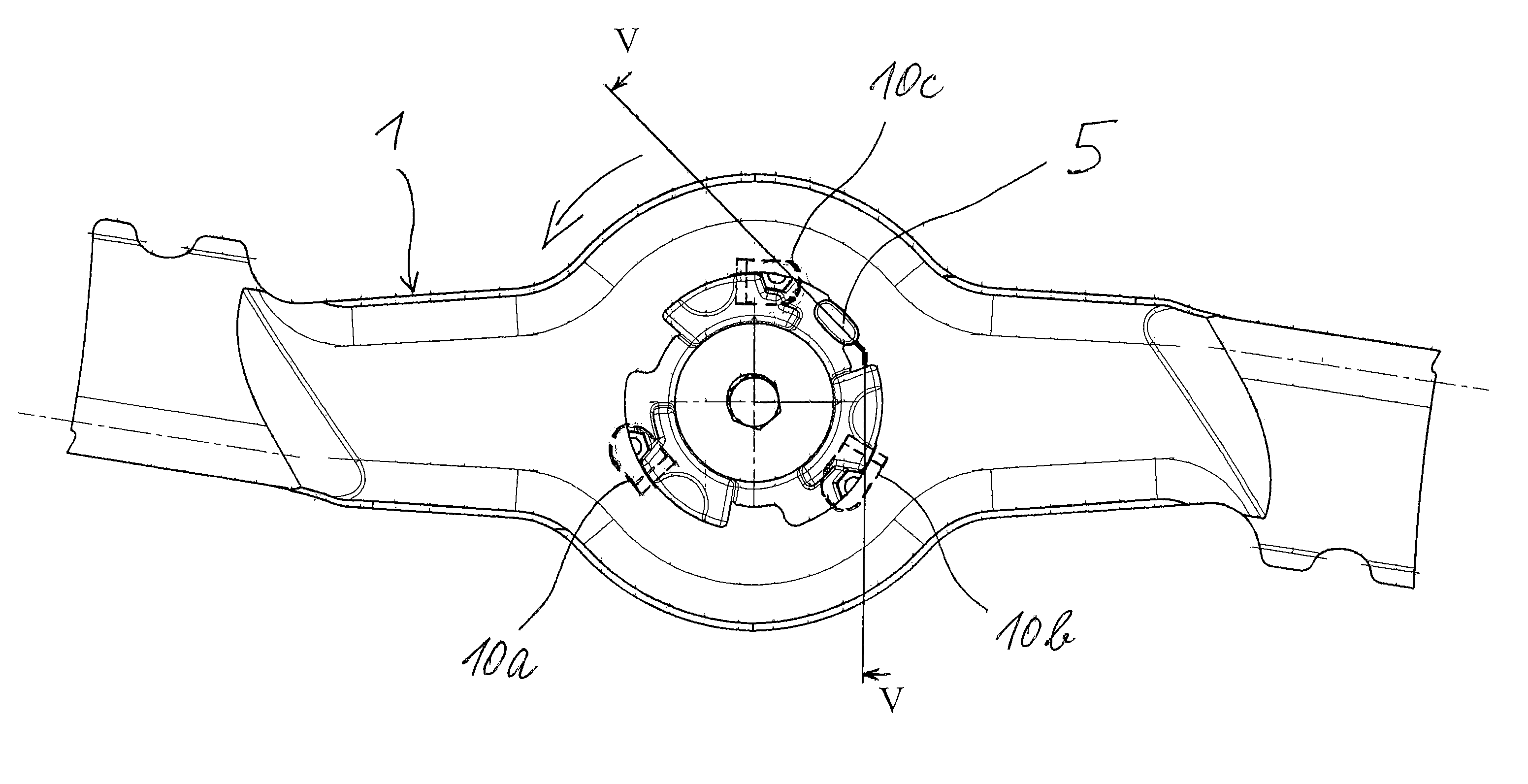
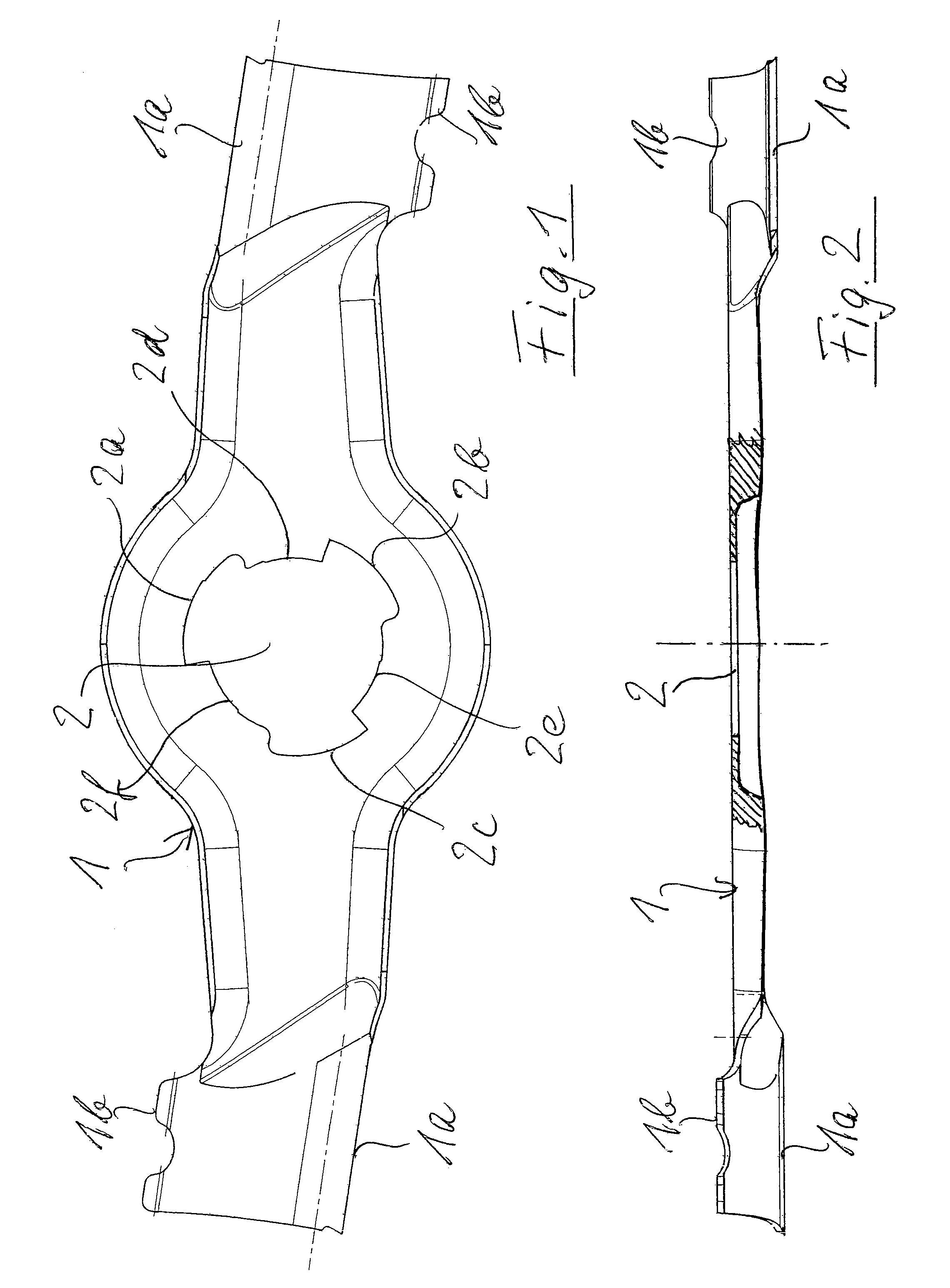
[0026]The knife in the form of a knife bar 1, shown in FIGS. 1 and 2, has a known form with respect to its outer contour and its profiling. In particular, the knife bar has two diagonally opposite outer cutting edges 1a, which end in upwardly bent wings 1b on their rear ends in the peripheral direction. A bore 2 is located in the center of the knife bar. According to the invention, this bore has on its periphery several recesses 2a, 2b, 2c and projections 2d, 2e, 2f, which interact with the knife carrier (to be described below) in the manner of a bayonet lock. This interaction can be seen in the following figures.

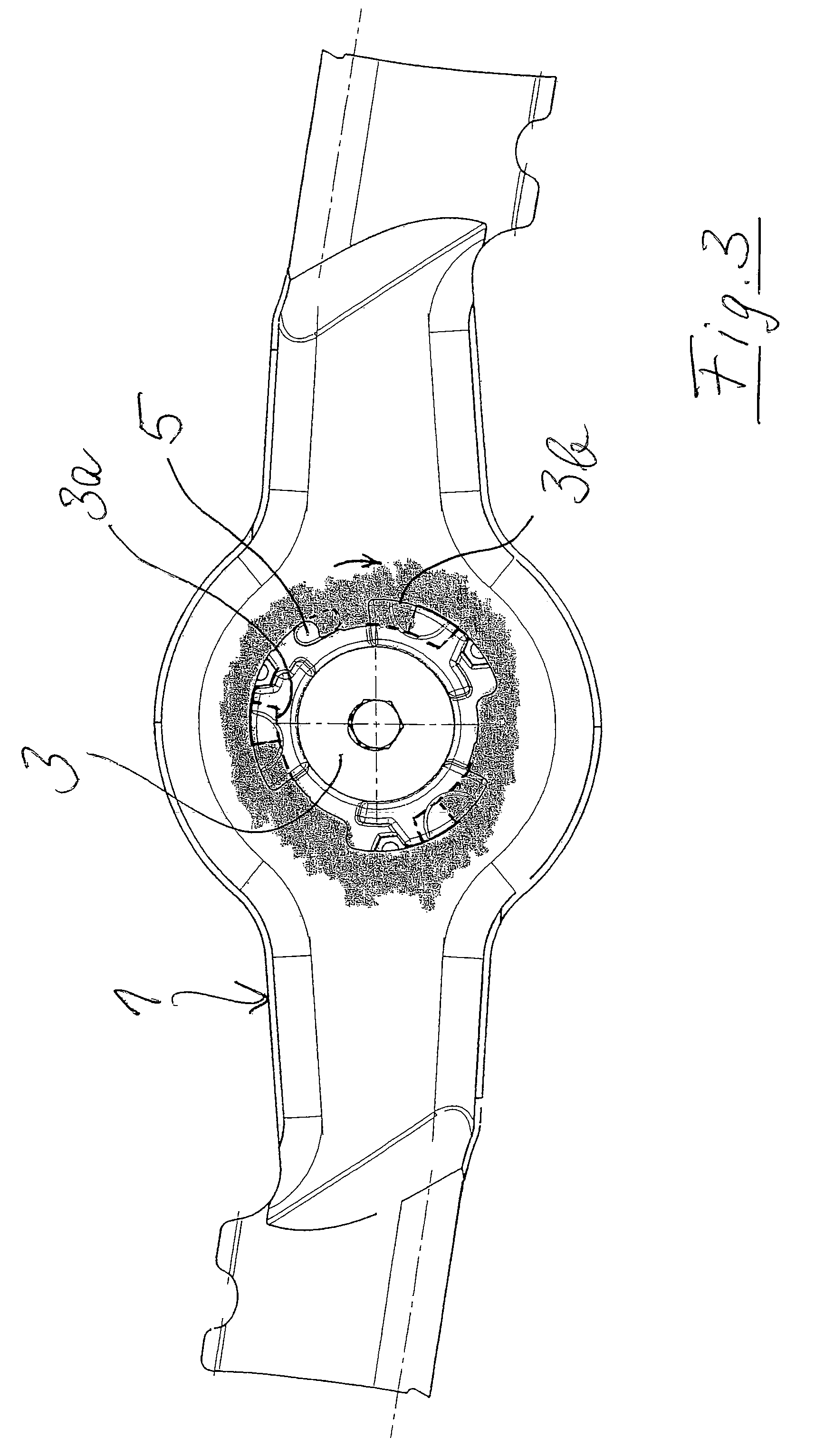
[0027]FIG. 3 shows an intermediate stage in which the knife bar is partially mounted on its knife carrier 3. It can be seen there that the knife carrier 3 has an axially projecting cylindrical band 3a over parts of its periphery. This band 3a corresponds to the inner peripheral sections 2d, 2e, 2f of the bore 2 of the knife bar and defines its axis of rotation. Alternativel...


PUM


Abstract

A cutting device, particularly a lawn mower, has at least one rotating knife mounted on a rotating, motor-driven knife carrier by a screwless, detachable connection. This connection is detachable by a relative rotation between the knife and the knife carrier. It is essential that the connection between the knife and its knife carrier be made by a centrally arranged bayonet lock and that this bayonet lock be locked in the closed position by an additional locking element.

Description

BACKGROUND OF THE INVENTION[0001]The invention relates to a cutting device, in particular, a lawn mower having at least one rotating knife, which is mounted on a rotating, motor-driven knife carrier by a screwless, detachable connection, the connection being detachable by a relative rotation between the knife and the knife carrier.[0002]In lawn mowers it is necessary to regrind the knives from time to time to ensure a smooth, clean cut of the grass. When the knives are mounted, this regrinding is only possible temporarily. Usually, the knives are removed and clamped in a special grinding device to maintain the correct cutting angle over the length of the knife.[0003]After a longer period of use, conventional screw connections for the knife are clogged with cut material and soil, so that it becomes more difficult to detach the knife. Thus, a screwless knife carrier is already known from German patent DE 195 20 618, having the features described at the outset, in which the knives can ...

Claims


Application Information

Patent Timeline
Patent Type & Authority Patents(United States)
IPC IPC(8): A01D63/00A01D34/68A01D34/73A01G3/053A01G3/06B26D1/36
CPCA01D34/73A01G3/0535A01G3/06
Inventor TREGER, CLAUDEBOUR, DANIEL
Owner WOLF OUTILS
Why Eureka
Try Eureka