Method and apparatus for a substantially coaxial injector element

a substantially coaxial and injector element technology, applied in the direction of lighting and heating apparatus, explosions, combustion types, etc., can solve the problems of inability to meet the demands of the thermal the face nut cannot survive the demanding environment of some systems, and the system is generally complex. , to achieve the effect of high reliability

Active Publication Date: 2006-10-24
THE BOEING CO
View PDF24 Cites 38 Cited by
  • Summary
  • Abstract
  • Description
  • Claims
  • Application Information

AI Technical Summary

Benefits of technology

[0015]It will also be understood that the present invention can be applied to various other applications besides rocket engines or injector systems for combustion systems. In particular, any application which would require two fluids to be injected into a common area can be used in conjunction with the present invention. In particular, any system which desires to provide a highly compact injector face that is both densely packaged with injector ports and highly reliable may be used in conjunction with the present invention.

Problems solved by technology

These systems are generally complex because they require an additional component to form the injector system.
Moreover, the fuel sleeves add an additional complex machined component.
In addition, the face nut cannot survive the demanding thermal environment in some systems.
Further disadvantages of these two systems include that they are not easily scaled down for smaller or more compact injector systems and engines.
Machining these components becomes significantly more complex and costly at smaller and smaller tolerances and sizes.
This system generally results in high injector post costs, while also making it more difficult to place the tabs properly on the oxidizer post as the oxidizer post size is reduced.

Method used


Image

  • Method and apparatus for a substantially coaxial injector element
  • Method and apparatus for a substantially coaxial injector element
  • Method and apparatus for a substantially coaxial injector element

Examples


Embodiment Construction

)

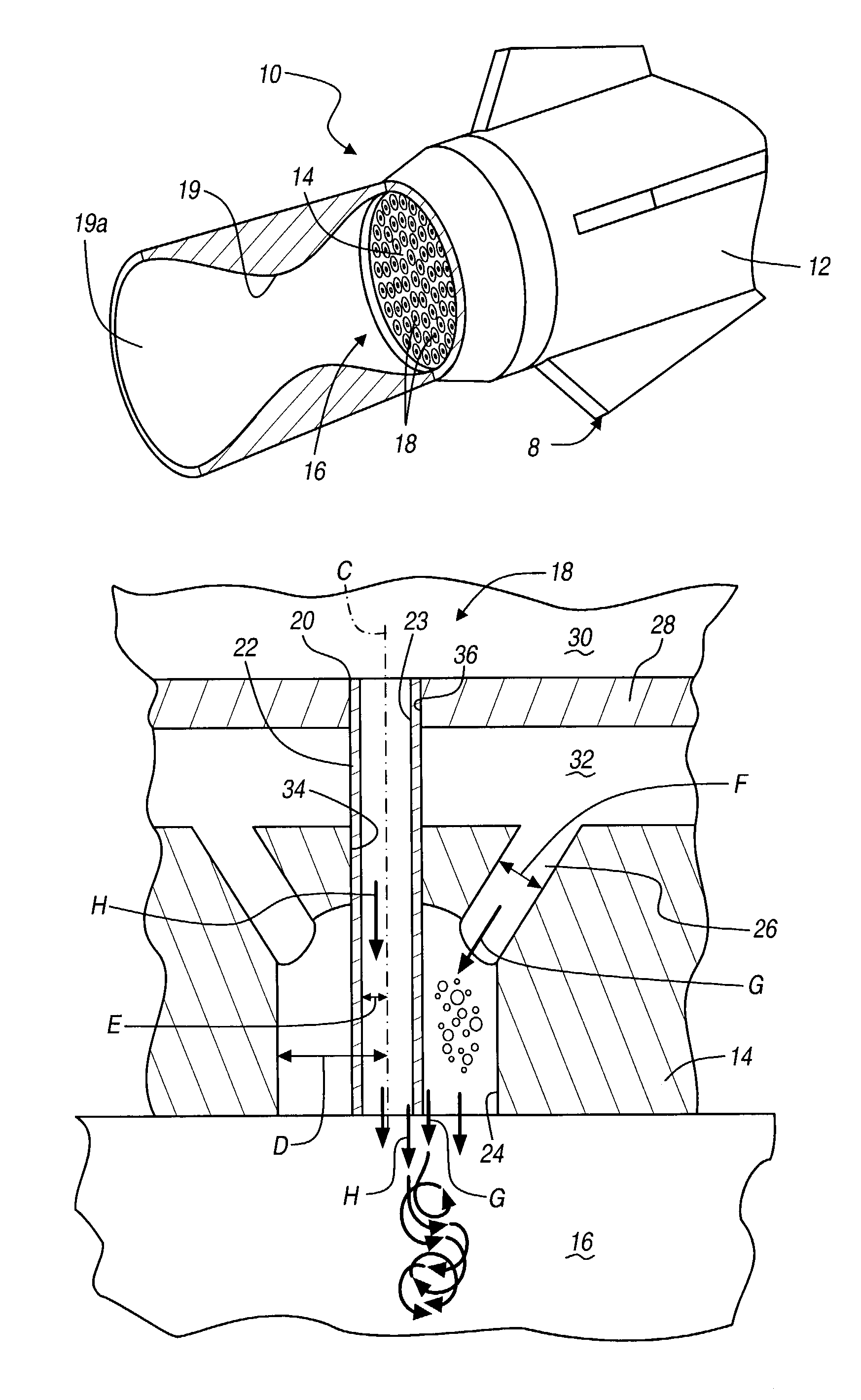
[0022]The following description of the preferred embodiment(s) is merely exemplary in nature and is in no way intended to limit the invention, its application, or uses. Although the following description describes the present invention exemplarily in conjunction with a rocket engine combustion system, the present invention will be understood not to be so limited. In particular, although the present invention as described is to provide a system to inject two propellants through an injector face into a combustion chamber, it will be understood that the present invention can be used to inject two fluids into any common container. Therefore, the present invention is not limited to solely being used with rocket systems.

[0023]With reference to FIG. 1, a rocket or spacecraft 8 includes a rocket engine 10 in accordance with a preferred embodiment of the present invention. The rocket engine 10 is provided with a fuel or propellant compartment or supply 12 and a face plate 14. The face plate...


PUM


Abstract

A system to provide a two piece robust fluid injector. According to various embodiments, the fluid injector is a fuel injector for a combustion engine. The injector includes two coaxially formed annuluses. One annulus is formed in a face plate and the second annulus or hole is defined by a tube extending through the face plate. The tube extends through the face plate in a portion of a through bore which also is used to define the second annulus. The second annulus is formed using a throughbore through which the tube extends. This allows the second annulus to always be formed inherently and precisely substantially coaxial with the first annulus. Moreover, the second annulus can be formed with a much greater tolerance than if other independent components needed to be added.

Description

STATEMENT REGARDING FEDERALLY SPONSORED RESEARCH OR DEVELOPMENT[0001]The Invention described herein was made in the performance of work under NASA Contract No. NAS8-40894 and is subject to the provisions of Section 305 of the National Aeronautics and Space Act of 1958 (72 Stat.435; 42 U.S.C. 2457).FIELD OF THE INVENTION[0002]The present invention relates to fuel injectors for combustion systems, and particularly for rocket combustion systems.BACKGROUND OF THE INVENTION[0003]In a gas combustion engine a fuel is generally combusted with an oxidizer. Both the fuel and the oxidizer are provided to a combustion chamber where the combustion occurs. The combustion may either be caused by an ignition spark or some other means for igniting the mixture.[0004]One system for providing the fuel and oxidizer to a combustion chamber involves providing a fuel inlet and an oxidizer inlet. In these cases, the fuel and oxidizer are provided through separate inlets or ports to the combustion chamber. T...

Claims


Application Information

Patent Timeline
Patent Type & Authority Patents(United States)
IPC IPC(8): F02K9/00F02K9/42F02K9/72F02K9/52
CPCF02K9/52
Inventor HORN, MARK D.MIYATA, SHINJIROFARHANGI, SHAHRAM
Owner THE BOEING CO
Why Eureka
Try Eureka