Scroll-type expander having heating structure and scroll-type heat exchange system employing the expander

a technology of expander and expansion system, which is applied in the direction of machines/engines, liquid fuel engines, light and heating apparatus, etc., can solve the problems of only about expansion efficiency, low expansion efficiency, and low efficiency of roll-type expander, and achieve high efficiency isothermal compression and small flow resistance. , the effect of simple mechanical structur

Inactive Publication Date: 2006-10-24
KOREA INST OF MACHINERY & MATERIALS
View PDF14 Cites 35 Cited by
  • Summary
  • Abstract
  • Description
  • Claims
  • Application Information

AI Technical Summary

Benefits of technology

[0023]The present invention provides a scroll-type expander that simultaneously performs expansion and re-heating such that highly efficient expansion that approximates isothermal expansion is realized and such that there is no reduction in efficiency caused by pressure loss occurring during the supply of an working fluid such as gas or steam to a center area of the scroll-type expander, and that minimizes a difference in temperature between a stationary scroll member and a orbiting scroll member, as well as a temperature distribution of a scroll wrap.
[0037]In the scroll heat exchange system of the present invention, the mechanical structure is simple, and compression and expansion are continuously performed such that there is almost no variation in torque and a flow direction of the operational fluid is unchanged. As a result, flow lines and regenerator structure may be realized such that flow resistance is small.
[0038]In addition, since the heat transfer area making contact with the working fluid in the compressor and expander is extremely large, highly efficient isothermal compression and expansion that approaches the ideal Stirling cycle is possible, and a heater and cooler may be made small or removed altogether such that dead volume is reduced to improve output. Finally, overall manufacturing costs are reduced by minimizing or removing the need for the heater.
[0039]In the scroll heat exchange system of the present invention, since the working fluid flow is in one direction, the working fluid heated in the heater is not re-heated following expansion, and the working fluid cooled in the cooler is not re-cooled following compression such that heat loss, flow resistance, thermal stress, etc. caused by anomalies in the cycle may be reduced.
[0040]In addition, since low temperature compression and high temperature expansion are realized as fully separated processes, high efficiency that approaches an ideal cycle may be obtained. Also, compression ratio control by the bypass line in the compressor is easy such that effective engine control is possible.
[0041]Finally, in the scroll heat exchange system of the present invention, since continuous, steady state driving is possible, there are almost no periodic temperature and pressure variations in the structural elements such that limitations on the selection of materials for and manufacture of the structural elements are significantly reduced, and low noise, low vibration, small size, and light weight may be realized as a result.

Problems solved by technology

The scroll-type expander, on the other hand, has not experienced widespread use.
As a result, efficiency is reduced by pressure loss when supplying the gas or steam such that while compression efficiency reaches up to 90%, expansion efficiency is only about 60˜70%.
These factors result in a reduction in efficiency by the generated friction, leakage, and increased vibration.
However, in the case where a gas of a low molecular weight is used as the working gas, leakage easily occurs such that it is extremely important to use a high performance gas seal.
However, the actual cycle is more like that shown in FIG. 12, which is significantly less efficient than the ideal case.
However, even if a sufficient number of heat transfer pins are mounted outside the cylinder, since the area of the inside surface of the cylinder walls making contact with the working gas is limited, it is difficult for the working gas to be heated or cooled isothermally.
This becomes increasingly problematic if the engine is made faster and to larger sizes, in which case the processes inside the cylinder becomes more adiabatic (no heat transfer) than isothermal (infinite heat transfer).
As a result, the flow resistance is increased and thermal efficiency is reduced.
Further, the thermal stress to the structural parts increases such that care must be given in selecting the materials for the parts and other limitations are given to manufacture of the device.
However, if the number of re-heating stages is increased, the fluid needs to be circulated between the boiler 305 and turbines 309 and 312, both the overall size of the assembly and equipment costs are increased, and operational control becomes complicated.
Accordingly, re-heating is typically performed one or two times, which places a limitation on the efficiency of the steam cycle.

Method used


Image

  • Scroll-type expander having heating structure and scroll-type heat exchange system employing the expander
  • Scroll-type expander having heating structure and scroll-type heat exchange system employing the expander
  • Scroll-type expander having heating structure and scroll-type heat exchange system employing the expander

Examples


first embodiment

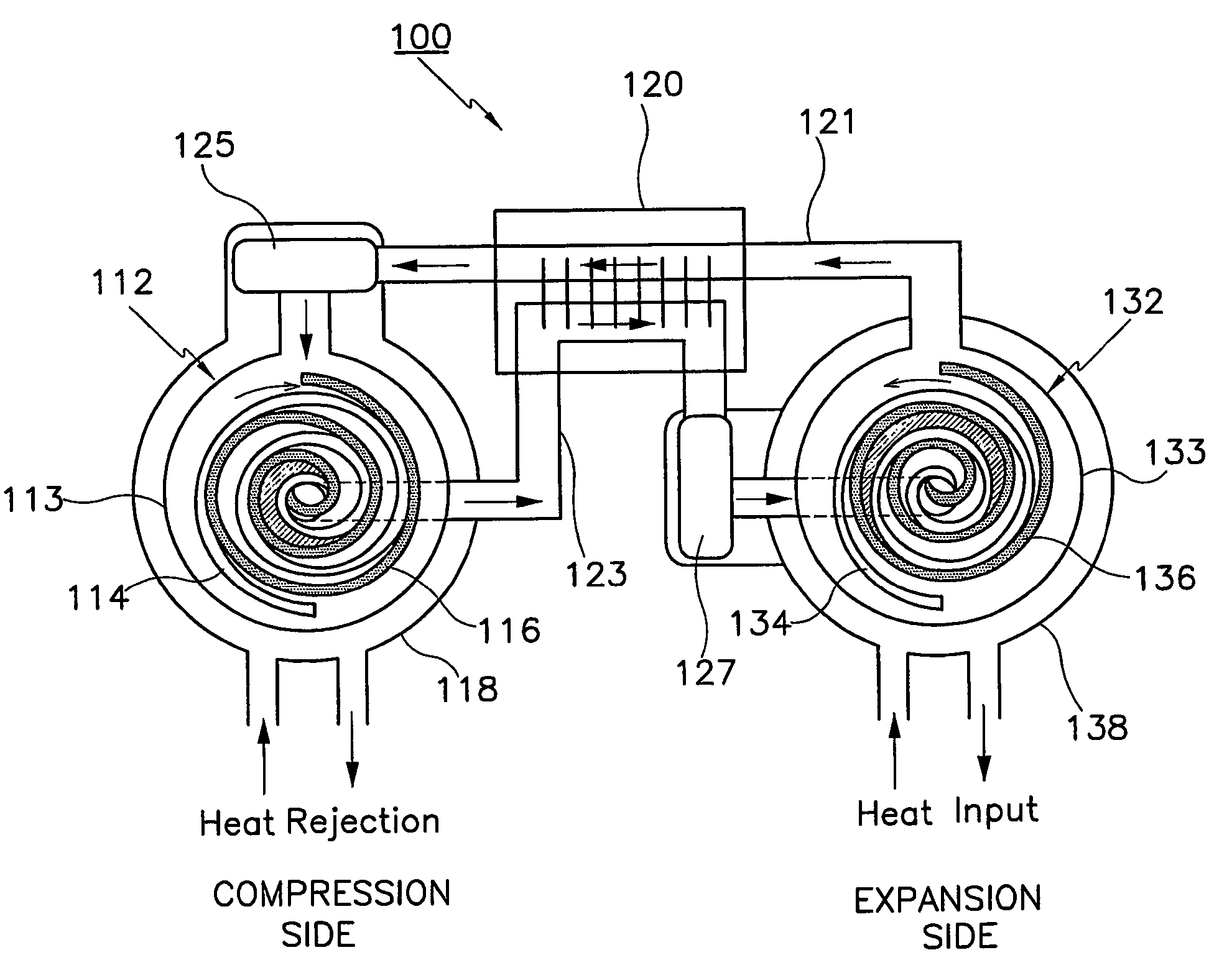
[0078]With reference to FIG. 4, a cooler 125 and a heater 127 may be further included in the scroll heat exchange system 100 according to the invention.

[0079]The cooler 125 is connected to the operational fluid inflow opening provided to the outer area of the scroll-type compressor 112, and acts to cool the working fluid that is supplied to the scroll-type compressor 112 after passing through the regenerator 120. The heater 127 is connected to the working fluid exhaust opening provided to the center area of the scroll-type expander 132, and acts to heat the working fluid that is supplied to the scroll-type expander 132 after passing through the regenerator 120.

[0080]When a temperature of the scroll-type expander 132 is higher than a temperature of the scroll-type compressor 112, the scroll heat exchange system 100 operates as an engine such that heat is received in the scroll-type expander 132 and heat is rejected from the scroll-type compressor 112 in the manner of a Stirling engin...

second embodiment

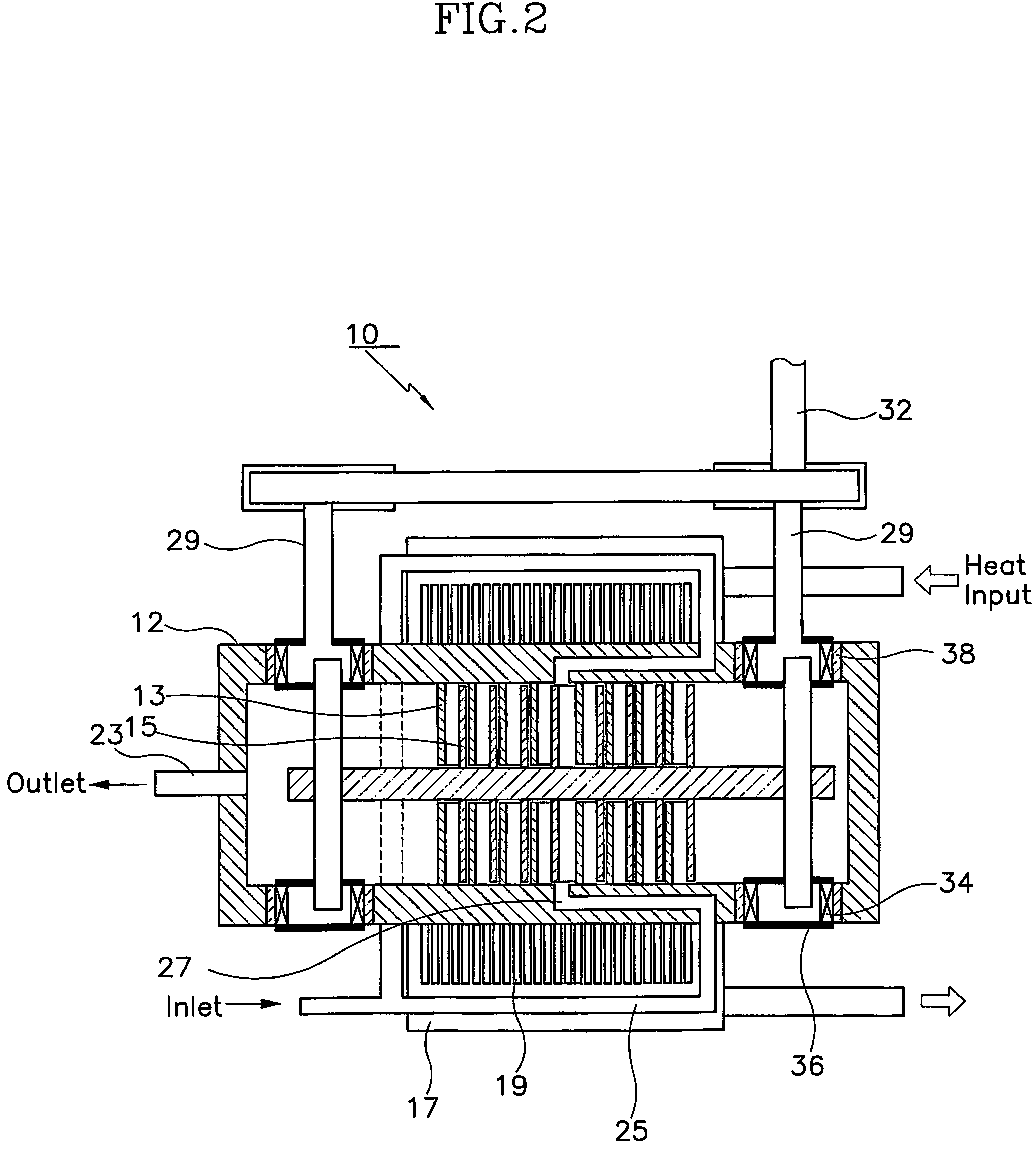
[0082]FIG. 5 is a sectional view of a scroll heat exchange system according to the present invention.

[0083]With reference to the drawing, a scroll heat exchange system 140 according to a second preferred embodiment of the present invention is basically the same in structure to the scroll heat exchange system 100 according to the first preferred embodiment of the present invention. However, a pair of stationary scroll members 143 and a pair of orbiting scroll members 145 are provided in a housing 142 of a scroll-type compressor 141, and a pair of stationary scroll members 153 and a pair of orbiting scroll members 155 are provided in a housing 152 of the scroll-type expander 151 such that an upsetting moment is not generated.

[0084]A plurality of cooling pins 149 are formed to an external surface of the housing 142 of the scroll-type compressor 141, and a plurality of heating pins 159 are formed to an external surface of the housing 152 of the scroll-type expander 151 such that cooling...

third embodiment

[0091]FIG. 6 is a schematic view of a scroll heat exchange system according to the present invention.

[0092]With reference to the drawing, in a heat exchange system according to a third embodiment of the present invention, a center scroll-type compressor 172 is provided to a middle area of the system. Also, a first scroll-type expander 174 of a higher temperature than the center scroll-type compressor 172 is connected to one side of the same, and a second scroll-type expander 176 of a lower temperature than the scroll-type compressor 172 is connected to another side of the same. The heat exchange system structured in this manner may be used as a Stirling refrigerator driven by Stirling engine.

[0093]That is, the combination of the high temperature first scroll-type expander 174 and the scroll-type compressor 172 operates as a Stirling engine, and the combination of the low temperature second scroll-type expander 176 and the scroll-type compressor 172 operates as a Stirling refrigerato...


PUM


Abstract

The present invention provides a scroll-type expander that simultaneously performs expansion and re-heating such that efficient expansion is realized and there is no reduction in efficiency caused by pressure loss occurring during the supply of an working fluid to the scroll-type expander, and that minimizes a difference in temperature between a stationary scroll member and a rotating scroll member, as well as a temperature distribution of a scroll wrap. The present invention also relates to a heat exchange system that uses a scroll-type expander to replace pistons in a conventional reciprocating Stirling engine or refrigerator with a pair of scroll-type compressor and expander such that the heat exchange system may be used as a Stirling engine or refrigerator. The present invention also provides a steam engine, in which a steam turbine in the conventional steam engine (Rankine system) is replaced with a scroll-type expander such that the steam cycle has both a re-heating cycle and a regeneration cycle.

Description

BACKGROUND OF THE INVENTION[0001](a) Field of the Invention[0002]The present invention relates to a scroll-type expander and a scroll-type compressor, and more particularly, to a scroll-type expander and a scroll-type compressor that include a stationary scroll member and a rotating scroll member to continuously perform expansion and compression of an working fluid. The present invention also relates to a scroll-type heat exchange system that includes a scroll-type expander and scroll-type compressor for use as a Stirling engine or refrigerator.[0003](b) Description of the Related Art[0004]Scroll device offers many advantages including high efficiency, low noise, low vibration, small size, and light weight. Scroll devices are widely used as a result of these advantages scroll-type compressor In more detail, with reference to FIG. 1, a stationary scroll member 30 of involute form and a rotating scroll member 40 are provided at a 180° phase difference. As a result, a series of crescen...

Claims


Application Information

Patent Timeline
Patent Type & Authority Patents(United States)
IPC IPC(8): F01K7/02F01C1/04F01C11/00F01C21/00F01K1/00F01K25/10F01K7/22F04C18/04F04C23/00F02G1/043F01K7/00F02B53/00F04C18/02F25B9/06F25B9/14
CPCF01C11/004F01K7/00F04C18/0223F04C23/003F25B9/06F25B9/14F02B53/00F25B2309/1401F01K27/00
Inventor KIM, YOUNG-MINSHIN, DONG-GILLEE, JANG-HEE
Owner KOREA INST OF MACHINERY & MATERIALS
Why Eureka
Try Eureka