Casing wear band and method of attachment

a technology of wear bands and casings, applied in the field of wear bands, can solve the problems of challenging the performance requirements of casings and the installation can place severe structural demands on casings, and achieve the effect of facilitating the frictional engagement of crimps and augmenting the frictional aspects of connection

Inactive Publication Date: 2006-10-24
NABORS DRILLING TECH USA INC
View PDF28 Cites 25 Cited by
  • Summary
  • Abstract
  • Description
  • Claims
  • Application Information

AI Technical Summary

Benefits of technology

[0017]While a purely mechanical method of obtaining interference through crimping is desirable for most applications, the present invention also anticipates applications where thermal and mechanical methods can be combined.
[0018]To facilitate the frictional engagement of the crimped wear band tool to the thick-wall pipe the inside surface of the wear band tool, at least over the section to be crimped, or the outer surface of the casing can be provided with a roughened surface finish. In a further embodiment, a friction enhancing material such as a grit epoxy mixture is disposed in the interfacial region of the crimped section. Similarly, various bonding materials can be disposed in the interfacial region prior to crimping to act as glues augmenting the frictional aspects of the connection once their shear strength is developed after setting.

Problems solved by technology

However, casing installation through deviated wellbores or by drilling with casing challenge the performance requirements of the casing.
Installation can place severe structural demands on casing since they must survive extended periods of time in contact with the borehole wall.

Method used


Image

  • Casing wear band and method of attachment
  • Casing wear band and method of attachment
  • Casing wear band and method of attachment

Examples


Embodiment Construction

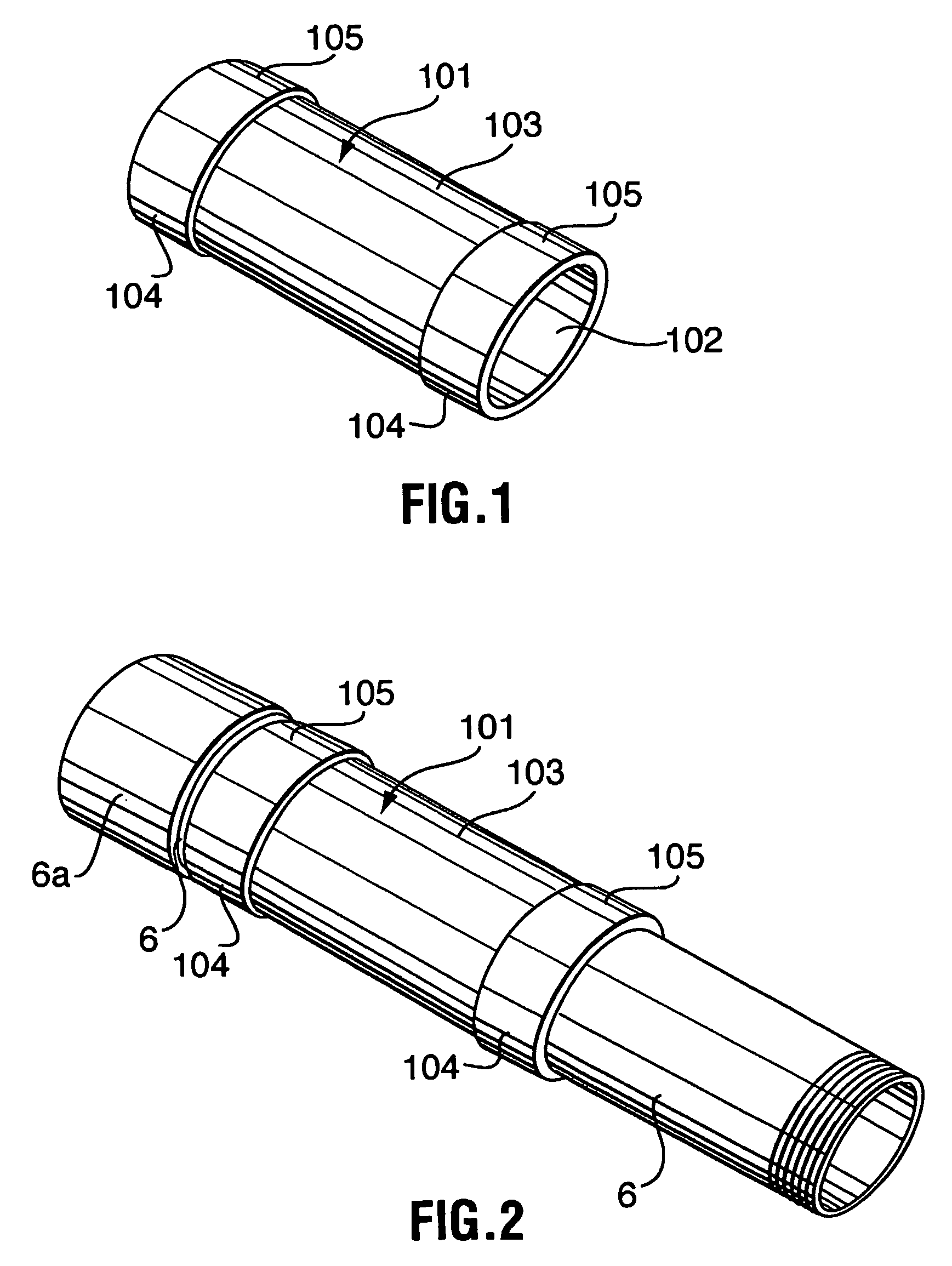
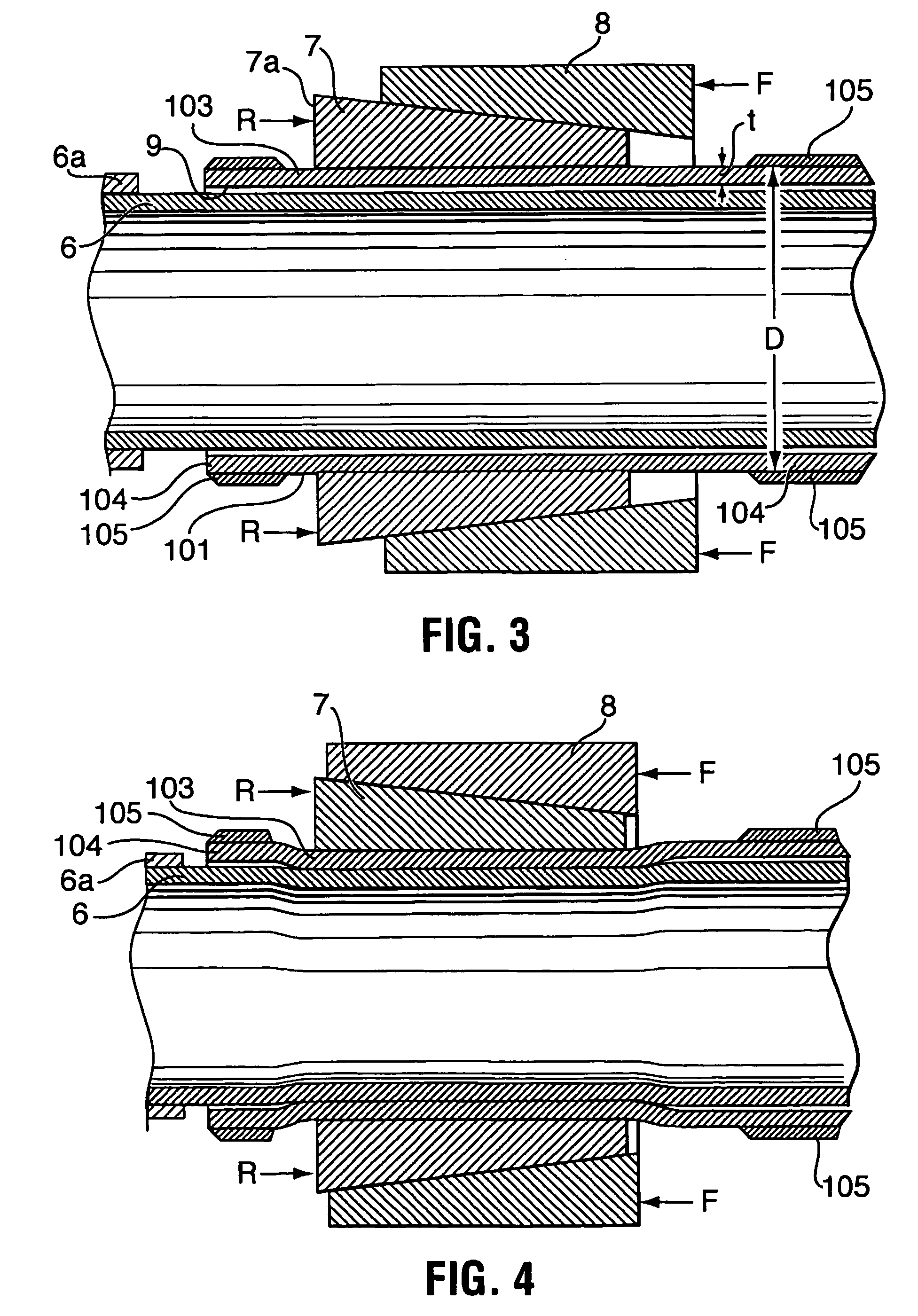
[0025]According to the present invention, a wear band tool is provided as shown in FIG. 1, and a method of crimping it to a thick-wall metal pipe when placed on the pipe as shown in FIGS. 2 to 4.

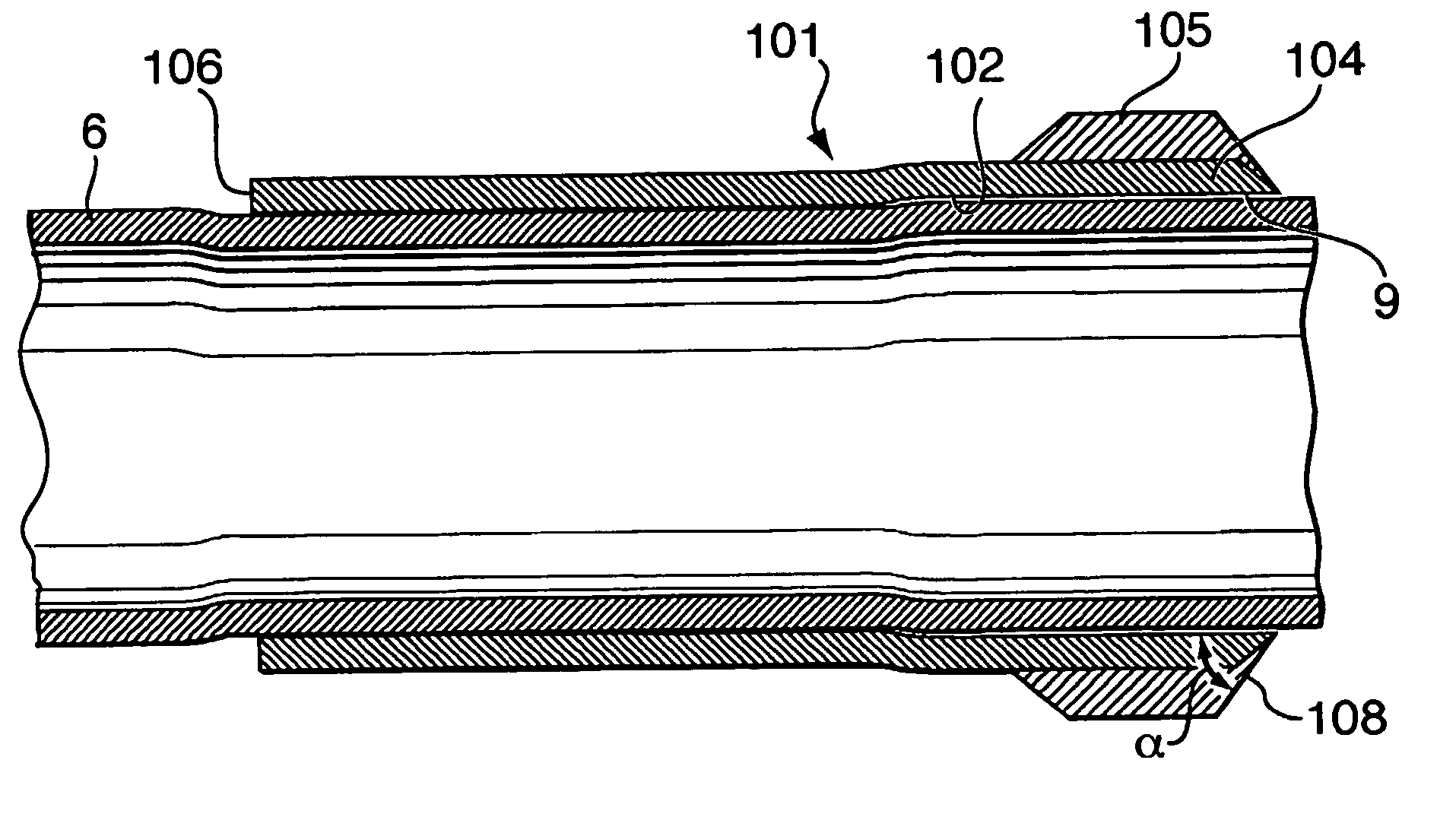
[0026]Referring to FIG. 1, a metal body 101 containing an internal bore 102, a cylindrical mid-section 103 forming a section suitable for crimping, and two end intervals 104 on which hard-faced wear bands 105 are placed. As shown, a concentric wear band 105 is placed at each end of the wear band tool forming slightly raised diameter intervals. These wear bands are formed by attaching hard-facing material as commonly known to the industry to metal body 101. The wear bands are selected to act as bearing surfaces and can withstand wear to a greater degree than the remainder of the wear band tool, the casing and casing couplers.

[0027]The cylindrical mid section and the end intervals are formed integral on the body and the internal bore passes through all of them. While the crimpable section in t...


PUM

PropertyMeasurementUnit
angleaaaaaaaaaa
angleaaaaaaaaaa
angleaaaaaaaaaa

Abstract

A crimpable wear band (105) tool has been invented for installation on casing (6), used in well bore drilling. A wear band (105) is provided having a cylindrical body which when coaxially placed over a pipe and substantially radially inwardly displaced at a plurality of points (i.e. crimped) about the circumference of a section of cylindrical body, attaches to the pipe to create a connection having structurally significant axial and torque load transfer capacity. When crimped according to the methods of the present invention, the load transfer capacity of the connection between the wear band (105) tool and the pipe (6) can be arranged to substantially prevent significant relative movement of the wear band tool on the pipe under loads that may be encountered when using one or more of the pipes as components of a tubular string used for drilling or running the casing in to complete a well bore.

Description

FIELD OF THE INVENTION[0001]The present invention relates to wear bands for casing a method of attachment to enable transfer of structurally significant axial and torsional loads between the wear band and pipe.BACKGROUND OF THE INVENTION[0002]Within the context of petroleum drilling and well completions, wells are typically constructed by drilling the well bore using one tubular string, largely comprised of drill pipe, then removing the drill pipe string and completing by installing a second tubular string, referred to as casing, which is subsequently permanently cemented in place. The installation of casing, in this typical construction requires that the casing be run into long boreholes, some having horizontal stretches. In these horizontal stretches, the casing must be installed by pushing it along the borehole. In so doing the casing is pushed in engagement with the borehole wall.[0003]Recent advances in drilling technology have enabled wells to be drilled and completed with a s...

Claims


Application Information

Patent Timeline
Patent Type & Authority Patents(United States)
IPC IPC(8): E21B17/10E21B7/20E21B17/16E21B29/00E21B43/10
CPCE21B7/20E21B17/1078E21B17/1085E21B29/00E21B43/10E21B17/16Y10T29/49913Y10T29/49934
Inventor SLACK, MAURICE WILLIAM
Owner NABORS DRILLING TECH USA INC
Why Eureka
Try Eureka