Liquid distributor for use in mass transfer column

a liquid distributor and mass transfer technology, applied in liquid handling, separation processes, combustion-air/fuel-air treatment, etc., can solve the problems of reducing the mass transfer and/or heat exchange between the liquid and the vapor, uneven horizontal distribution of the liquid stream, and difficulty in ensuring the uniform horizontal distribution of liquid at low liquid flow rate, so as to facilitate the horizontal distribution of liquid

Active Publication Date: 2006-10-24
KOCH GLITSCH INC
View PDF25 Cites 45 Cited by
  • Summary
  • Abstract
  • Description
  • Claims
  • Application Information

AI Technical Summary

Benefits of technology

[0009]In one particular aspect, the present invention is directed to a liquid distribution system comprising an elongated feed box and a plurality of elongated liquid distribution troughs in fluid flow communication with the feed box. The troughs may desirably be spaced apart and preferably lie in a common plane in parallel relationship to each other. In one embodiment, the troughs may underlie the feed box and openings are provided in a floor and / or one or both side walls of the feed box to deliver liquid from the feed box to each of the troughs. In another embodiment, the troughs may extend outward from opposed side walls of the feed box and openings are provided in the side walls to allow liquid to flow from the feed box to the troughs. The troughs may have a square, rectangular, circular, oval or other configuration when viewed in vertical cross section. Each trough may also include openings positioned in a floor and / or one or both side walls of the trough to allow liquid to exit from the trough. A baffle distributor is positioned to receive the liquid exiting from each trough and facilitate the horizontal distribution of the liquid prior to delivery of the liquid to an underlying mass transfer bed, such as a bed of random, structured or grid-type packing.
[0011]The channels each have an overflow weir, preferably of a saw-toothed design, that provides for the controlled discharge of any overflow of liquid from the channels. A drip edge having a similar saw-toothed design extends downwardly from the trough to receive liquid traveling along the outer surface of the trough. The drip edge is preferably positioned in vertical alignment with the channel so that liquid drips off the drip edge and falls into the channel for horizontal distribution prior to entry into the underlying mass transfer bed. The described liquid distributor provides for good liquid mixing and horizontal distribution of the liquid at low liquid flow rates as well as high liquid flow rates.

Problems solved by technology

Uneven horizontal distribution of the liquid stream as it enters the packing bed is undesirable because it reduces the area of contact between the liquid and vapor and thus decreases the mass transfer and / or heat exchange between the liquid and vapor.
One problem associated with known types of liquid distributors is the difficulty in ensuring uniform horizontal distribution of liquid at low liquid flow rates.

Method used


Image

  • Liquid distributor for use in mass transfer column
  • Liquid distributor for use in mass transfer column
  • Liquid distributor for use in mass transfer column

Examples


Embodiment Construction

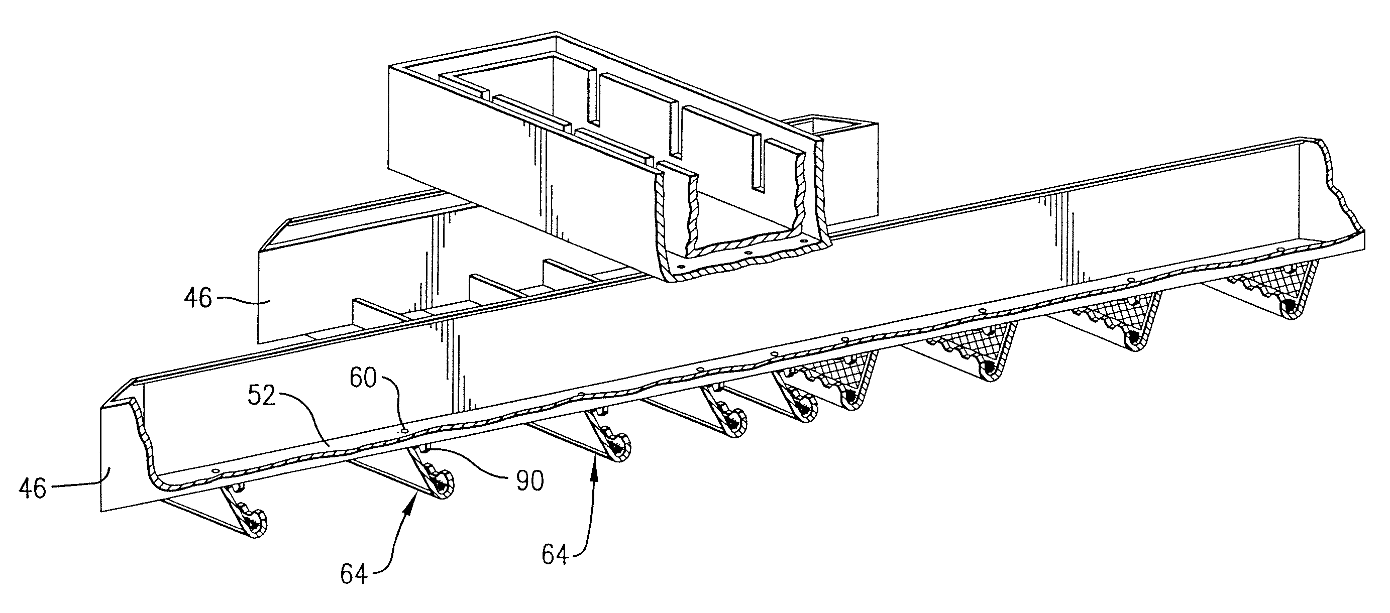
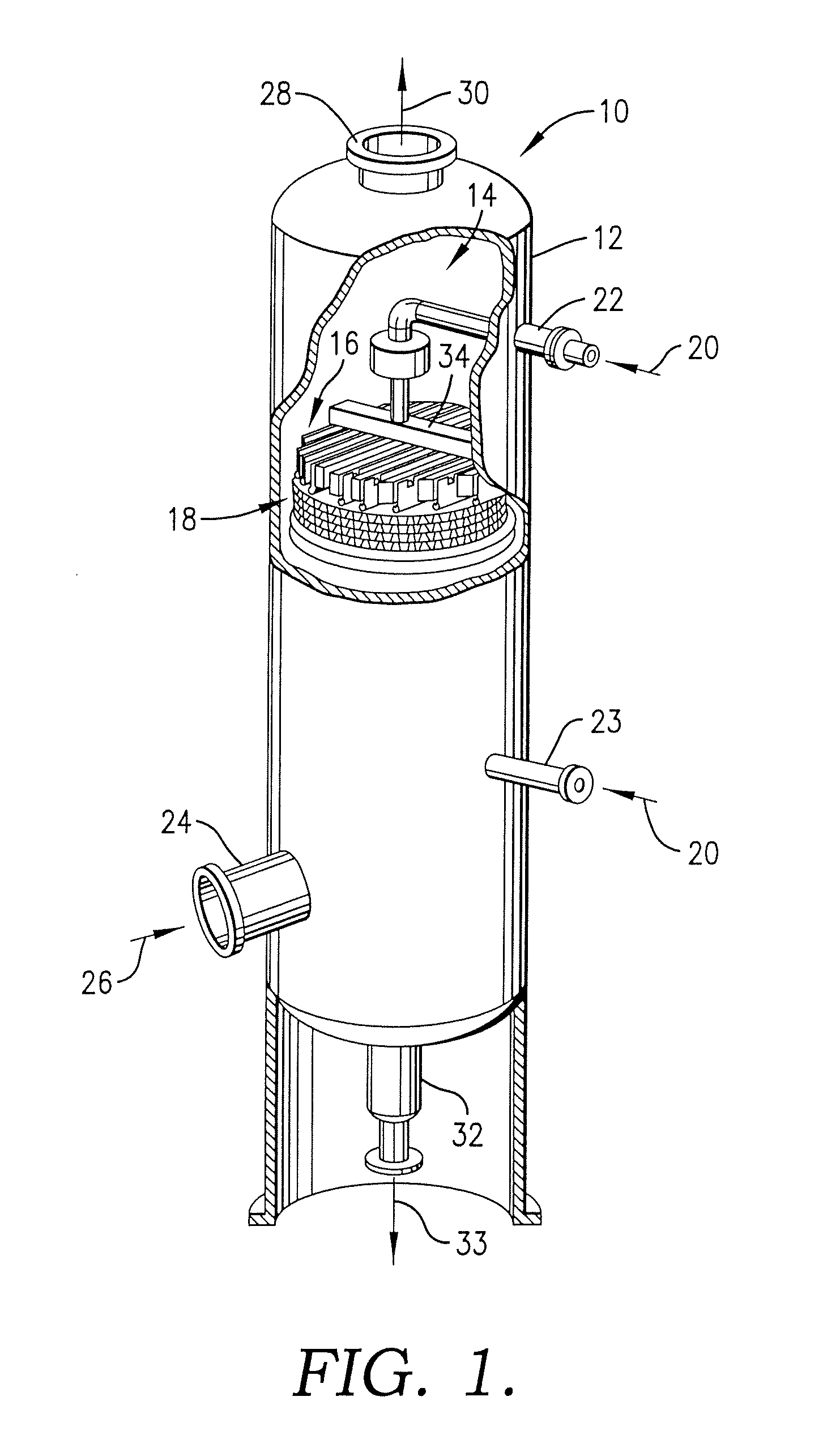
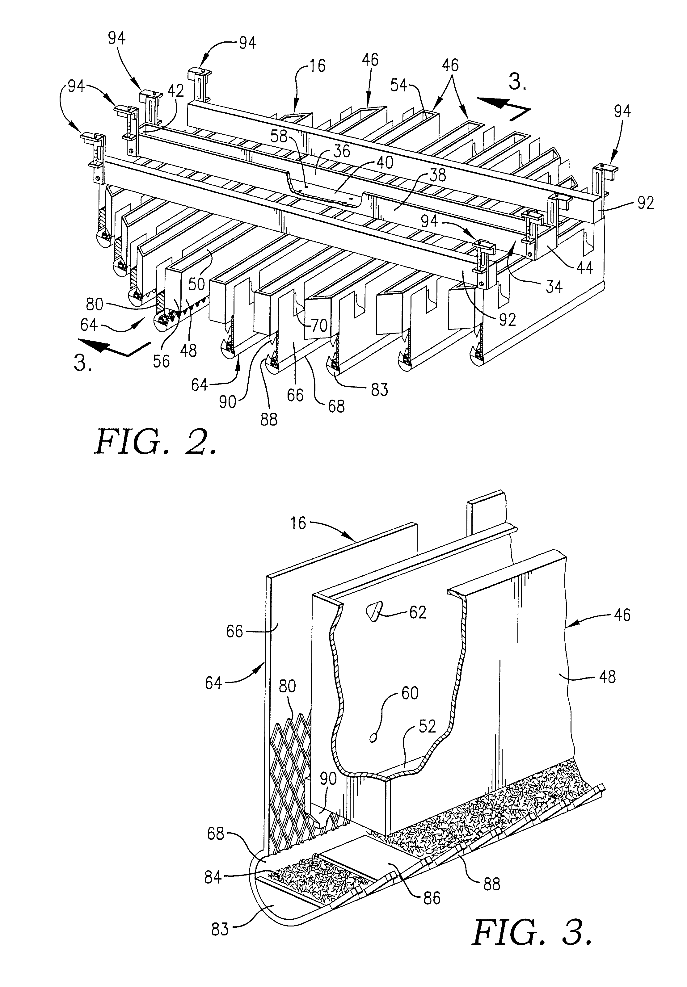
[0036]Turning now to the drawings in greater detail, and initially to FIG. 1, a mass transfer or heat exchange column is designated generally by the numeral 10 and includes an upright cylindrical shell 12 that defines an open interior region 14 in which one or more liquid distributors 16 of the present invention and one or more mass transfer beds 18 are located. The liquid distributor 16 is used to facilitate a more uniform horizontal distribution of one or more descending liquid streams as it enters the upper end of the underlying mass transfer bed 18. The mass transfer bed comprises one or more types of mass transfer devices, including but not limited to those conventionally known as structured, grid or random packing.

[0037]Column 10 is of a type used to process liquid and vapor streams, including to obtain fractionation products. Although column 10 is shown in a cylindrical configuration, other shapes, including polygonal, may be used. Column 10 is of any suitable diameter and he...


PUM

PropertyMeasurementUnit
angleaaaaaaaaaa
areaaaaaaaaaaa
permeableaaaaaaaaaa

Abstract

A flow distributor for liquid descending in a vertically elongated process column having an internal space. The distributor is made up of an elongated liquid distribution trough configured and arranged for being mounted in a process column in a position to extend across the internal space thereof. The trough has outer walls defining an elongated, longitudinally extending internal fluid distribution chamber and includes outlet holes which extend through the walls at locations permitting liquid to escape laterally outwardly from the trough. The distributor also includes a baffle distributor structure made up of an elongated, downwardly extending distributor plate member disposed adjacent the trough in a position such that at least a portion of a surface thereof is contacted by liquid escaping from said hole. The distributor also includes an elongated, fluid receiving element attached at a lower edge portion of said plate member presenting an elongated fluid distribution channel extending longitudinally of the plate member.

Description

CROSS-REFERENCE TO RELATED APPLICATION[0001]Priority benefits under 35 U.S.C. §119(e) are claimed in this application from provisional application Ser. No. 60 / 529,509, filed on Dec. 15, 2003, the entirety of the disclosure of which is hereby specifically incorporated herein by this reference thereto.BACKGROUND OF THE INVENTION[0002]1. Field of the Invention[0003]The present invention relates generally to mass transfer and heat exchange columns and, more particularly, to liquid distributors used in such columns and methods of distributing liquid using such liquid distributors.[0004]2. The Prior Art Background[0005]In mass transfer and heat exchange columns, liquid and vapor streams are brought into contact with each other to effect mass transfer and / or heat exchange between the liquid and vapor. One or more beds of structured or random packing are typically used to facilitate intimate contact between the liquid and vapor and thereby enhance the desired mass transfer and / heat exchange...

Claims


Application Information

Patent Timeline
Patent Type & Authority Patents(United States)
IPC IPC(8): B01F3/04B01D3/00B67D
CPCB01D3/008
Inventor DOLLIE, YUSUF OMARMULLER, JUERGENNIEUWOUDT, IZAKGOMMERS, JOHNKASHAMMER, RAINERENDER, CHRISTOPH
Owner KOCH GLITSCH INC
Why Eureka
Try Eureka