System and method of providing emergency response to a user carrying a user device

a user device and emergency response technology, applied in the field of providing emergency response to users carrying user devices, can solve the problems of user inability to communicate the nature of emergency to a human advisor, user cannot activate their system, user cannot receive assistance, etc., and achieve the effect of overcoming inadequacies

Active Publication Date: 2006-10-24
KRAUS MARK W +1
View PDF42 Cites 63 Cited by
  • Summary
  • Abstract
  • Description
  • Claims
  • Application Information

AI Technical Summary

Benefits of technology

[0010]The subject invention overcomes the inadequacies that characterize the related art systems. The subject invention allows the user to establish communication using internet protocols directly through the user device with the contact over the Internet. So long as the device is within arms reach, the user requests immediate assistance by notifying the monitoring database and the monitoring database assess the emergency and alert the contacts or emergency personnel.

Problems solved by technology

If the user encounters an emergency or incident at a distance far from the speakerphone, the user is not able to communicate the nature of the emergency to a human advisor.
Therefore, the user will not activate their system for fear of being unable to communicate the nature of the emergency effectively and being embarrassed when emergency personnel arrive.
Another limitation of the related art device is that the user cannot receive assistance if the user is not inside the home or is too far away to activate the device.
However, the '456 patent does not establish communication between the oversight authority and the user device using the Internet and does not utilize voice-over internet protocols to transmit the information or establish communication.
However, no related art systems combine monitoring and tracking of the user with the user being able to notify contacts of emergency or incidents by establishing communication over the Internet.

Method used


Image

  • System and method of providing emergency response to a user carrying a user device
  • System and method of providing emergency response to a user carrying a user device
  • System and method of providing emergency response to a user carrying a user device

Examples


Embodiment Construction

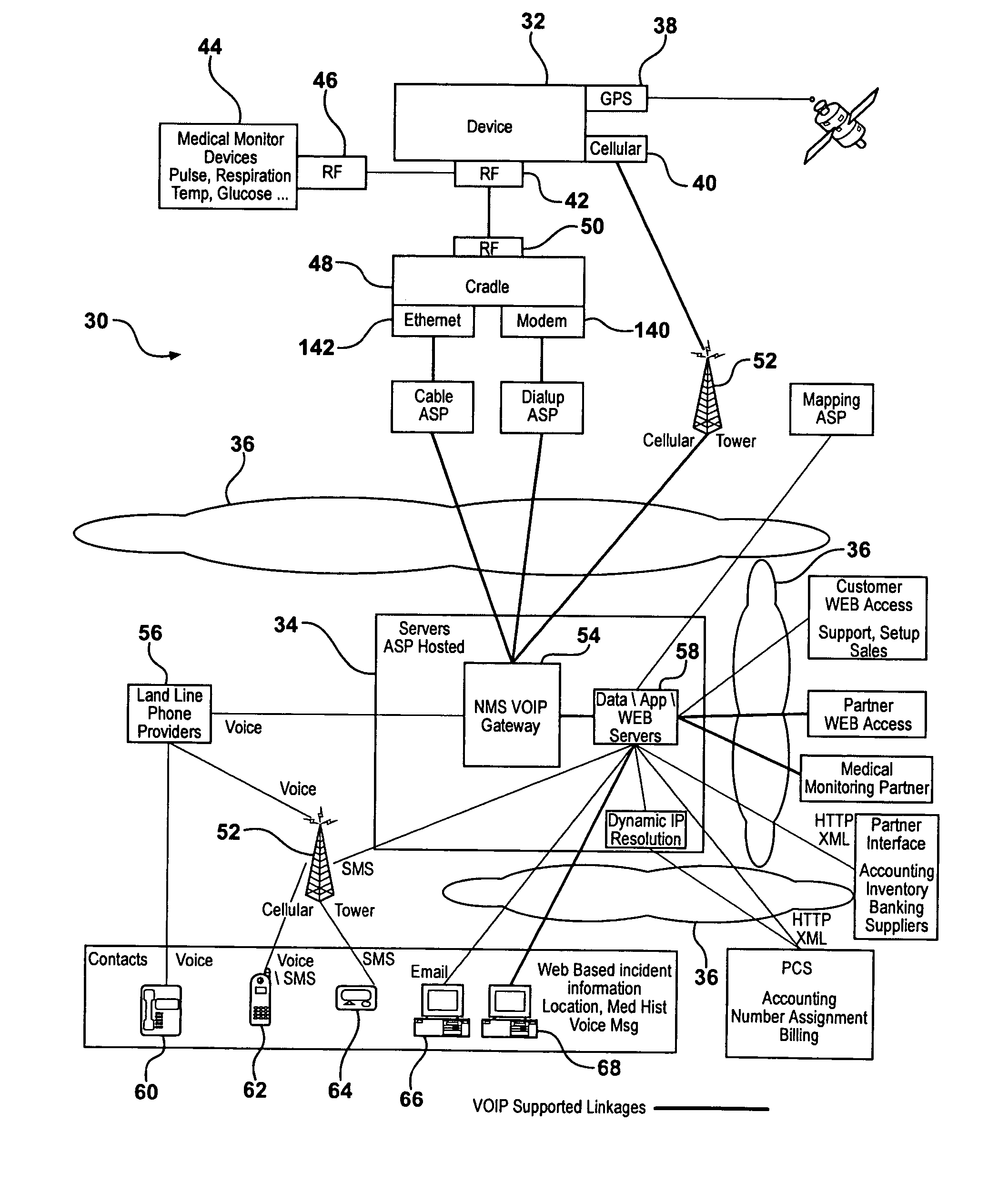
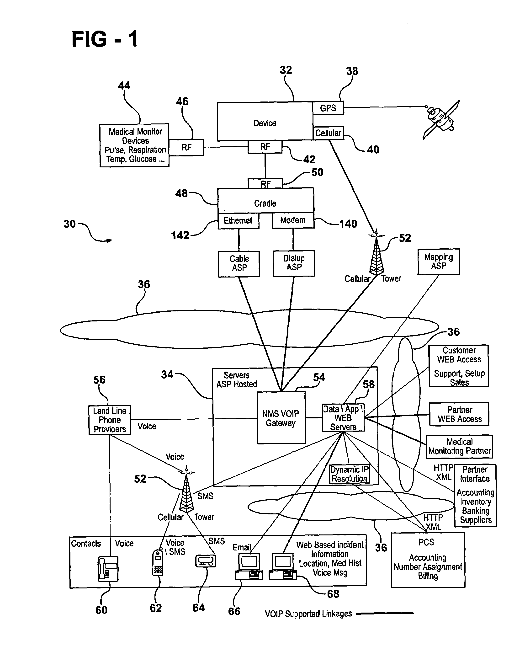
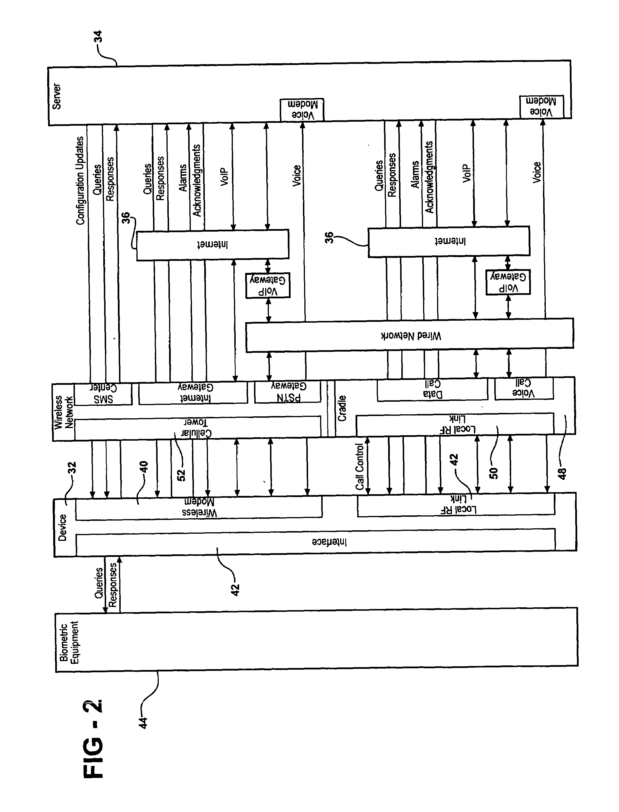
[0035]Referring to the Figures, wherein like numerals indicate like parts throughout the several views, an emergency alert system is disclosed generally at 30 in FIG. 1. The emergency alert system 30 includes a user device 32 carried by a user (not shown) and a monitoring database 34. The user device 32 and the monitoring database 34 communicate via internet protocols (IP) over the Internet 36. The Internet 36 is illustrated in FIG. 1 as generically cloud-shaped and interconnecting various components. It is to be appreciated that IP includes transmission control protocols (TCP) and any other connectionless, packet switching protocol that may be employed to communicate across the Internet 36. The preferred internet protocol is TCP / IP, but the subject invention contemplates use with other internet protocols, such as file transfer protocol (FTP). The Internet 36 refers to a system of interconnected networks that connects computers around the world and that communicate via TCP / IP, as un...


PUM


Abstract

The subject invention provides a method of providing emergency response to a user carrying a user device (32). The method establishes a monitoring database (34) including identifications for a plurality of user devices (32) and user information associated with each of the user devices (32). The monitoring database (34) includes a list of contacts to be contacted in an emergency for each user of each user device (32). An internet protocol (IP) address is established for the monitoring database (34) and for each user device (32). One of the user devices (32) is selected in the database and at least one of the selected user device (32) or at least one contact from the list of contacts associated with the selected user device (32) is notified of the emergency. The communication between the monitoring database (34) and the selected user device (32) is established over the Internet (36) using internet protocols to notify the selected user device (32) and / or the contact.

Description

CROSS-REFERENCES TO RELATED APPLICATIONS[0001]This application claims priority to U.S. Provisional Patent Application No. 60 / 489,022 filed Jul. 22, 2003.BACKGROUND OF THE INVENTION[0002]1. Field of the Invention[0003]The subject invention relates to a method of providing emergency response to a user carrying a user device and more specifically to establishing communication between the user device and a monitoring database over the Internet to provide such responses.[0004]2. Description of the Related Art[0005]Various related art methods and devices are known for providing emergency response to a user and for monitoring the user. One such method connects a device to the public switched telephone network (PSTN) and the device acts as a speakerphone. If the user encounters an emergency or incident at a distance far from the speakerphone, the user is not able to communicate the nature of the emergency to a human advisor. When the emergency is unknown, emergency personnel, such as police...

Claims


Application Information

Patent Timeline
Patent Type & Authority Patents(United States)
IPC IPC(8): G08B1/08G08B25/01G08B25/08H04M11/04H04M15/00H04W4/90H04W76/00
CPCG08B25/016G08B25/08H04L67/025H04L67/306H04L67/322H04M2242/04H04W4/22H04W76/007G08B25/001G08B25/005H04W76/50H04W4/90H04L67/61G08B25/10
Inventor KRAUS, MARK WTOENJES, PAUL G
Owner KRAUS MARK W
Why Eureka
Try Eureka