Polarized lightwave reflectometry method (POTDR)

a lightwave reflectometry and polarized lightwave technology, applied in the direction of instruments, optical apparatus testing, structural/machine measurement, etc., can solve the problems of limited accuracy and insufficient application for certain applications, and achieve the effect of advantageous compromise and good accuracy

Active Publication Date: 2006-10-24
DRAKA COMTEQ BV
View PDF2 Cites 18 Cited by
  • Summary
  • Abstract
  • Description
  • Claims
  • Application Information

AI Technical Summary

Benefits of technology

[0007]The use of all of the above characteristics enables the method of the invention to be quantitative with very good accuracy over an extended range of values for polarizatio...

Problems solved by technology

The methods proposed can be described as being semi-quantitative insofar as firstly by giving a value for the polarization mode dispersion coefficient ...

Method used


Image

  • Polarized lightwave reflectometry method (POTDR)
  • Polarized lightwave reflectometry method (POTDR)
  • Polarized lightwave reflectometry method (POTDR)

Examples


Embodiment Construction

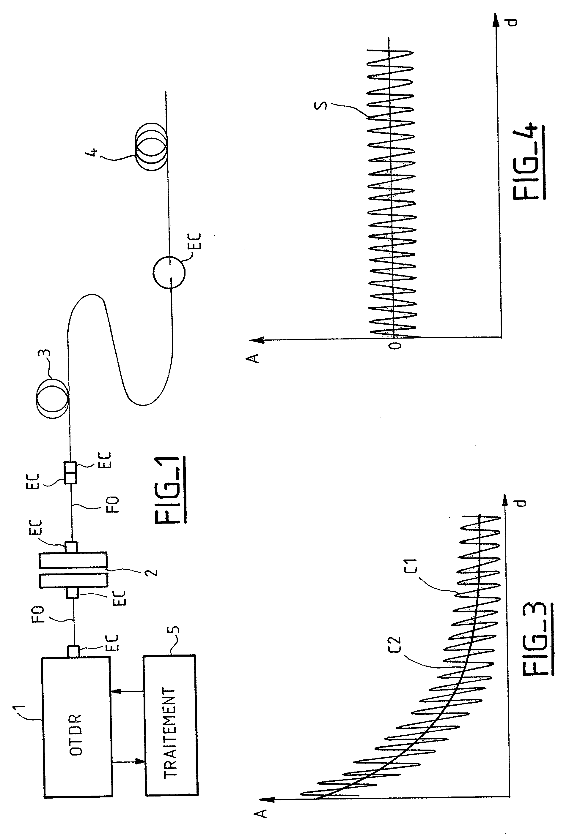
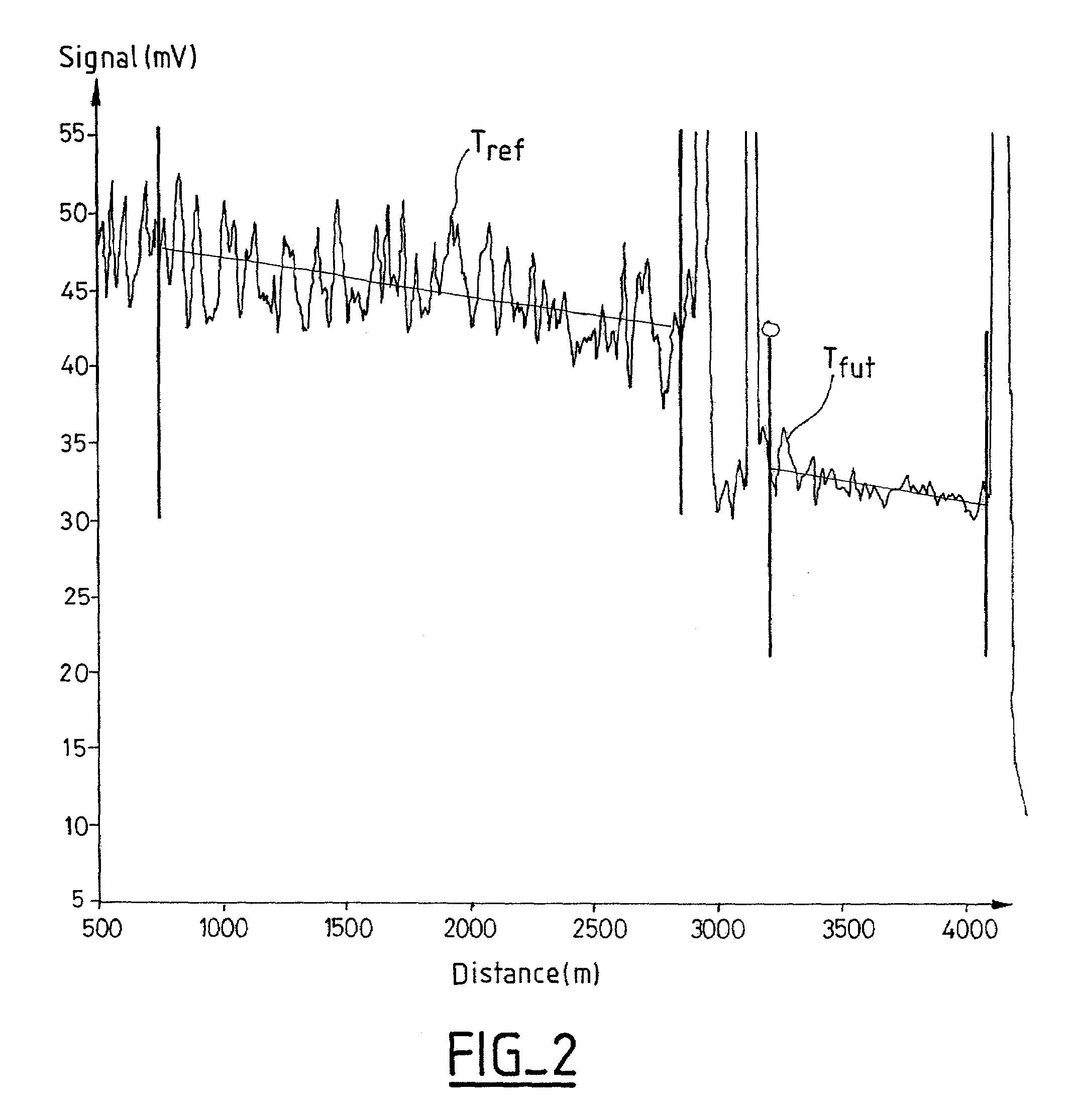
[0021]The invention is described below in greater detail for one of its aspects. In a preferred aspect of the invention, the polarized lightwave reflectometry method is applied to an optical fiber to be tested whose polarization mode dispersion coefficient is to be determined, in particular both for verifying the uniformity of polarization mode dispersion in the optical fiber under test, and secondly for optionally selecting good segments of the optical fiber, i.e. optical fiber segments having a low polarization mode dispersion coefficient. The method includes a step of sending a plurality of linearly polarized light signals into the optical fiber to be tested, preferably two such signals. The light signals present a determined mutual angular offset so that the overall relative noise remains independent of any rotation of polarization in the optical fiber under test. The representations of the light signals on the Poincarre sphere are independent of one another, thus ensuring a con...


PUM


Abstract

A polarized lightwave reflectometry method including the steps of sending at least two polarized light signals into the optical fiber to be tested, the signals presenting a determined angular offset relative to each other so that the polarization mode dispersion coefficient remains independent of any rotation of polarization in the optical fiber under test; extracting a scalar parameter of the relative noise type for each trace obtained by back-scattering of the light signal; and estimating the polarization mode dispersion coefficient by a function having a single scalar input, which function is of the type based on exponentials and has the form exp (a+bP+cP−1).

Description

BACKGROUND OF THE INVENTION[0001]The invention relates to the field of polarized lightwave reflectometry methods, also known as polarization optical time domain reflectometry (POTDR). Polarized lightwave reflectometry or POTDR makes it possible to obtain at least a qualitative estimate of the polarization mode dispersion (PMD) of optical fibers having a high degree of mode coupling, with dispersion being expressed in picoseconds per root kilometer (ps / km1 / 2). POTDR makes it possible to verify uniformity of PMD along optical fibers. This makes it possible to identify and select good segments of an optical fiber (i.e. segments presenting a low PMD coefficient). Since PMD in an optical fiber is due to birefringence in said optical fiber, analyzing a polarized lightwave that has passed along an optical function makes it possible, qualitatively, to evaluate the birefringence of said optical fiber, and consequently to derive a qualitative estimate of its PMD. PMD can be evaluated either l...

Claims


Application Information

Patent Timeline
IPC IPC(8): G01N21/00G01M11/02G01M11/00
CPCG01M11/3181
Inventor FAYOLLE, PHILIPPELUMINEAU, YVESBOUQUET, GREGORYDUREL, VANESSA
Owner DRAKA COMTEQ BV
Why Eureka
Try Eureka