Image forming apparatus featuring upward and downward toner carrying paths

a technology of toner carrying path and image forming apparatus, which is applied in the field of image forming apparatus, can solve the problems of increasing the frequency of locking the rotation of the flexible screw constituting the carrying means, affecting the stability of the carrying means, and affecting the accuracy of the image forming apparatus, etc., and achieves the effect of stable carrying and reduced cos

Inactive Publication Date: 2006-10-24
CANON KK
View PDF10 Cites 18 Cited by
  • Summary
  • Abstract
  • Description
  • Claims
  • Application Information

AI Technical Summary

Benefits of technology

[0022]In consideration of the foregoing, an object of the present invention is to provide an image forming apparatus capable of stable carrying without clogging by a carried substance. Preferably there is provided an image forming apparatus capable of powder carrying without difficulty even in case that one of powder carrying directions is an upward carrying direction, at a reduced cost.

Problems solved by technology

Also as the waste toner is unstable in the composition for example by the mixing of paper dusts, the waste toner may fluctuates significantly in the fluidity and is very difficult to handle in the carrying means.
However, in case the waste toner carrying path is bent excessively, or is relatively long with an upward carrying, or in case the amount of the carried waste toner is excessively large, the waste toner forms agglomerates in the carrying path because of the deteriorated carrying property of the waste toner, thereby increasing the frequency of locking the rotation of the flexible screw constituting the carrying means.
Also, in case the external diameter of the flexible screw is made larger to increase the carrying capacity for the waste toner, the flexible screw loses flexibility and the carrying path inevitably results in a larger radius in the curvature thereof, thus hindering compact designing of the apparatus.
Also, since the flexible screw carries the waste toner by rotation under friction with the internal wall of the tube or the pipe constituting the external wall, there results a concern for a loss of durability by abrasion in a contact portion between the flexible screw and the internal wall of the tube or the pipe.
For obtaining a sufficient durability, which is the same as the service life of the apparatus, it is necessary to select a tube or a pipe resistant to abrasion, leading to a higher component cost.
However, in an image forming apparatus or a full-color image forming apparatus of toner replenishing type, it is required to stably carry the waste toner without clogging over a prolonged period despite of the deteriorated carrying property of such waste toner and also to stably carry a large amount of the waste toner, and, particularly in a full-color apparatus, the amount of the waste toner becomes very large because of the presence of four developing devices, and the aforementioned waste toner carrying apparatus utilizing the flexible screw is not adequate for collectively carrying all the waste toners upwards to a waste toner recovery container.
However, in the full-color apparatus or a toner replenishing type, such vertical layout, in which the waste toner recovery container of a large capacity is positioned below the waste toner outlet of the cleaning device for recovering the discharge waste toner by dropping, is associated with a drawback of rendering the image forming apparatus itself bulky.
However, in case of carrying the waste toner upwards by providing a screw in a carrying tube as described in Japanese Patent Application Laid-open No. 04-116869, the waste toner is difficult to carry at an upper connecting portion of the carrying tube because it is inclined upwards, and a mere connection of the carrying tubes results in a clogging of the toner at the connecting portion.
Also the toner transfer at the connecting portion of the carrying tubes is usually achieved by forming a connecting portion at a bottom face of the carrying tube and transferring the toner by the weight thereof to a downstream carrying tube, but, in case a connecting portion is formed at a side face of the carrying tube, the carrying power at such transfer portion becomes lower as the weight of the toner cannot be utilized for transfer to the carrying tube of the downstream side.
On the other hand, an increase in the carrying power at such transfer portion may result in a toner clogging.

Method used


Image

  • Image forming apparatus featuring upward and downward toner carrying paths
  • Image forming apparatus featuring upward and downward toner carrying paths
  • Image forming apparatus featuring upward and downward toner carrying paths

Examples


embodiment 1

[0043](Embodiment 1)

[0044](1) Example of Image Forming Apparatus

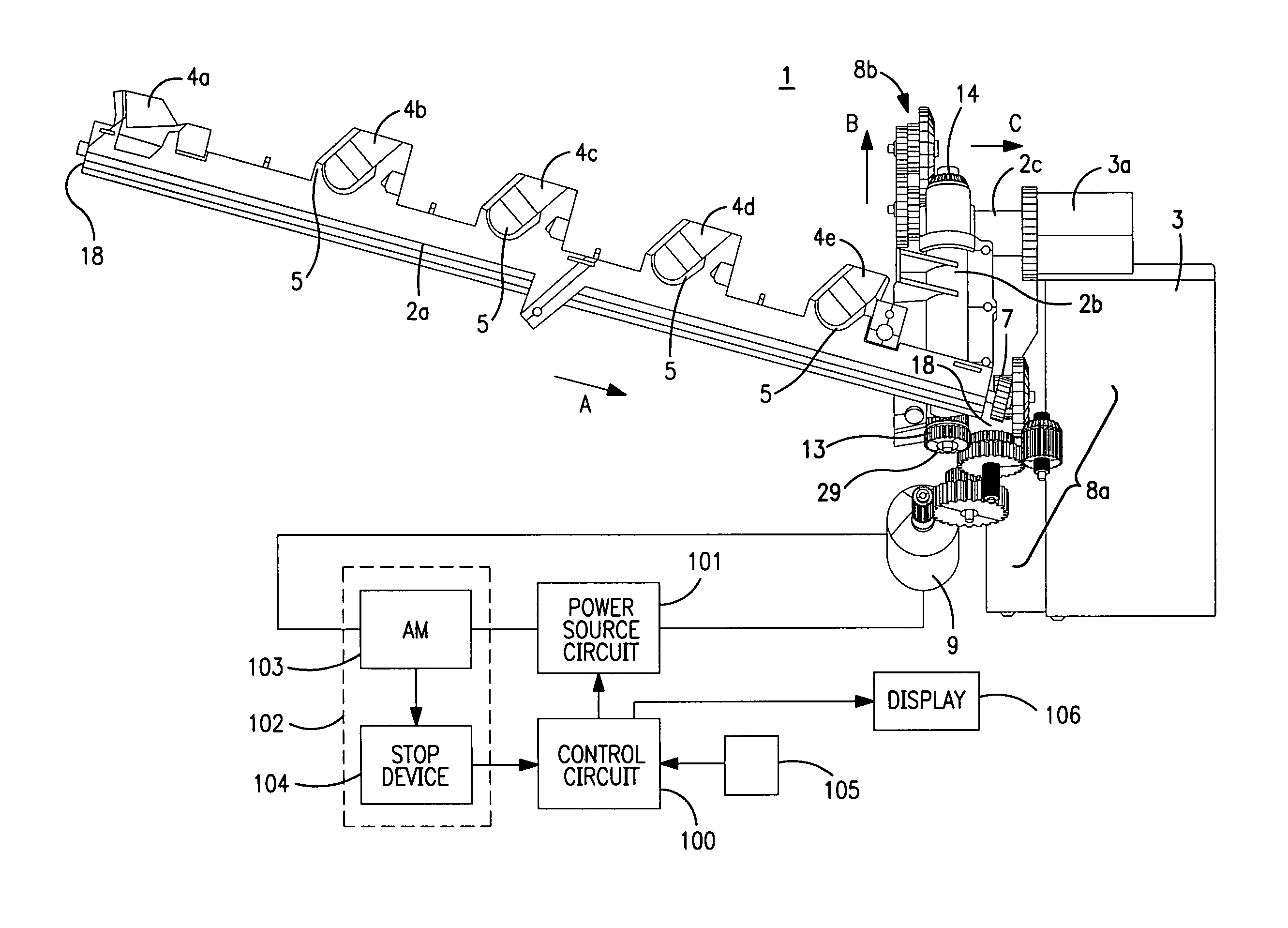
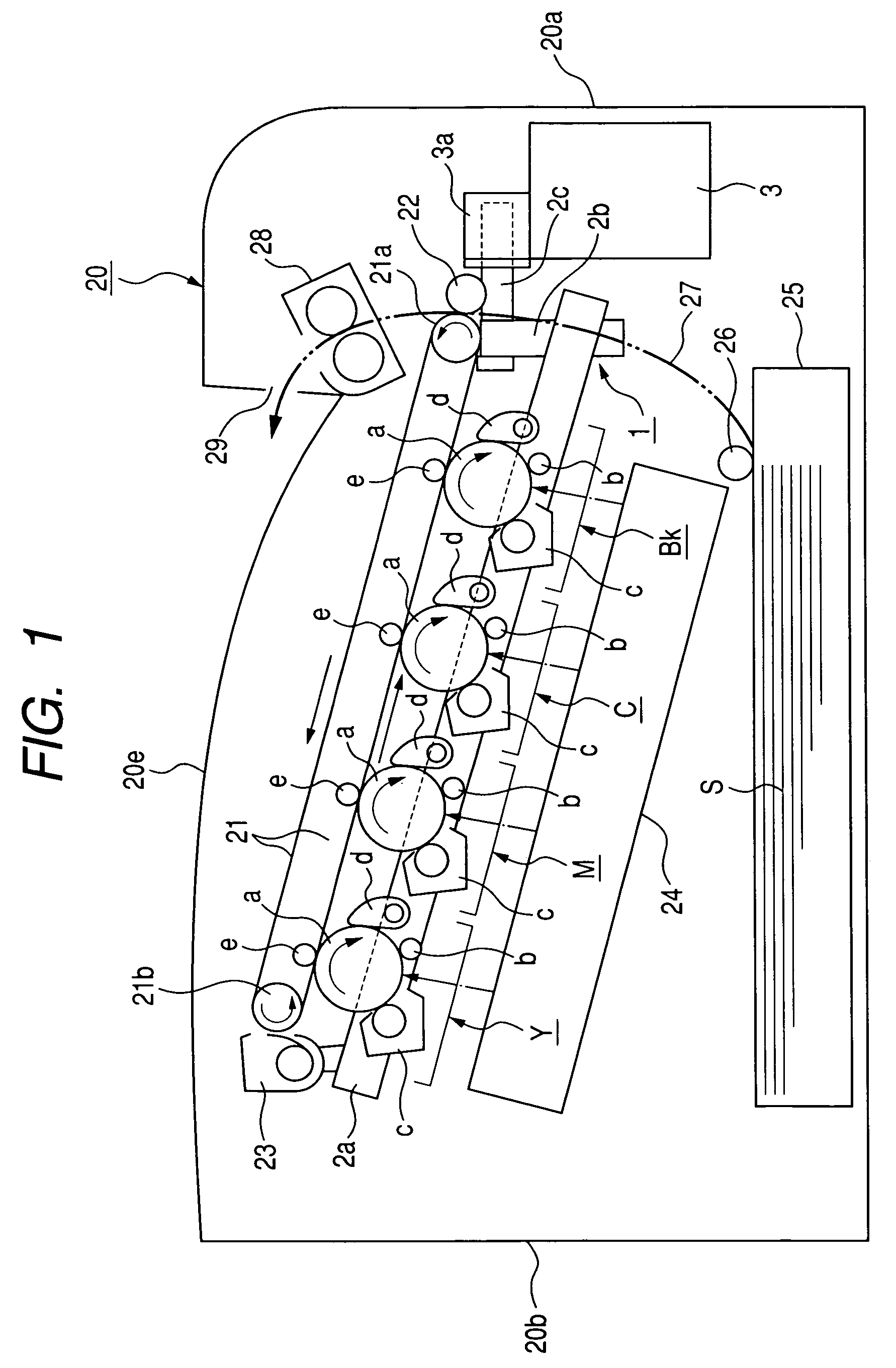
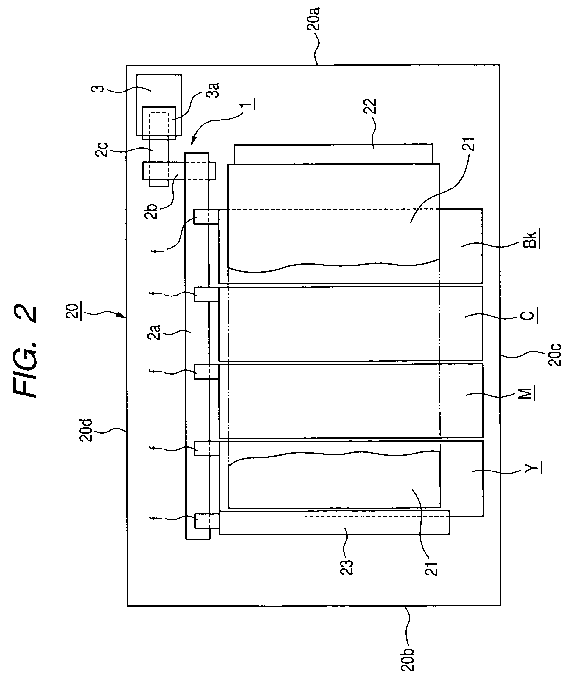
[0045]FIGS. 1 and 2 are schematic views showing the configuration of an image forming apparatus, in which a powder carrying apparatus of the present invention is applied as a waste toner carrying apparatus for carrying waste toner, discharged from an image forming mechanism, to a recovery portion.

[0046]The image forming apparatus of the present embodiment is a tandem-type color LBP (color laser beam printer) utilizing an electrophotographic process of transfer type. FIG. 1 is a lateral schematic view showing principal parts of an image forming mechanism, and FIG. 2 is a schematic plan view of the principal parts of the image forming mechanism.

[0047]Reference numeral 20 indicates an outer casing of the main body of the image forming apparatus, and reference numerals 20a, 20b, 20c, 20d and 20e respectively indicates a front plate, a rear plate, a left side plate, a right side plate and a upper plate of the casing 20.

[0048...


PUM


Abstract

An image forming apparatus, in which carrying paths for carrying the toner discharged from image forming portion are mutally connected, is capable of stable operation with satisfactory toner carrying at the connecting portion and not causing toner clogging. Preferably the image forming apparatus is low in cost and capable of smooth toner carrying even in case a toner carrying direction is an upward carrying direction. The image forming apparatus includes a plurality of toner carrying paths incorporating toner carrying screws, wherein an aperture is formed on a lateral face of each of the carrying paths, and, an aperture of an upstream carrying path and an aperture of a downstream carrying path are mutually opposed to connect the plurality of carrying paths. An angle formed by a toner carrying direction of the downstream toner carrying path and a gravitationally downward direction is larger than that in the upstream toner carrying path, and a carrying amount per unit time of the toner carrying screw of the downstream toner carrying path is made to be larger than a conveying amount per unit of the carrying screw in the upstream toner carrying path.

Description

BACKGROUND OF THE INVENTION[0001]1. Field of the Invention[0002]The present invention relates to an image forming apparatus such as a copying apparatus of a recording apparatus of an electrophotographic process, adapted for use of a waste toner carrying apparatus which carries a waste toner, discharged from an image forming mechanism, to a recovery portion.[0003]2. Related Background Art[0004]In an image forming apparatus for example of an electrophotographic method of transfer type, a waste toner, which is not transferred from a photosensitive member to a recording material or an intermediate transfer belt but is discharged, remains in a cleaning device for the photosensitive member, though it is not illustrated.[0005]For disposing of the waste toner accumulating in the cleaning device, various means and configurations are conceived as follows:[0006]1) In case the image forming apparatus has a detachable process cartridge which including a developing device and a cleaning device, t...

Claims


Application Information

Patent Timeline
Patent Type & Authority Patents(United States)
IPC IPC(8): G03G21/10
CPCG03G21/105
Inventor TSURUSAKI, TERUAKI
Owner CANON KK
Why Eureka
Try Eureka