Vibration-type measurement pickup for measuring media flowing in two medium-lines, and inline measuring device having such a pickup

a technology of medium-line and pickup, which is applied in the direction of mass flow measurement devices, measurement devices, instruments, etc., can solve the problems of increasing technical complexity, difficult to manage, and affecting the accuracy of measurement, and achieves high zero-point stability, high cost-favorable manufacturing, and high accuracy of measurement

Active Publication Date: 2006-10-31
ENDRESS HAUSER FLOWTEC AG
View PDF7 Cites 52 Cited by
  • Summary
  • Abstract
  • Description
  • Claims
  • Application Information

AI Technical Summary

Benefits of technology

[0010]Considering the above-mentioned disadvantages in the case of balance measurement systems of the described kind, an object of the invention is to provide a vibration-type measurement pickup, which can, on the one hand, have flowing through it simultaneously two media, which differ measurably from on another in at least one physical property, for example the mass flow rate, the density of the medium and / or the temperature of the medium, and which, on the other hand, nevertheless has a good zero-point stability.
[0014]An advantage of the measurement pickup of the invention is, among other things, that, in spite of the fact that it can be manufactured comparatively cost-favorably, it nevertheless exhibits a very high accuracy of measurement, especially also a very high zero-point stability.

Problems solved by technology

This can, as a result of the mechanical coupling between the individual measuring tubes, lead to considerable errors in the measured balance of the two medium streams, for example, thus, the measured mass flow rate difference, as discussed, for example, also in the already mentioned U.S. Pat. No. 6,457,372.
However, such a predominantly calculations-based compensation, which essentially only subsequently eliminates the measurement errors caused by the different oscillation amplitudes, leads, on the one hand, to an increased technical complexity as regards the construction of the exciter mechanism and sensor arrangement, as well as also regarding the construction of the measuring device electronics processing the measurement signals, as well as regards the hardware and also the software.
Furthermore, it has been found, that the imbalances unavoidably associated with the non-uniform changes of the oscillation characteristics of the measuring tubes can lead to significant problems as regards the zero-point stability of the measurement pickup, which then are scarcely manageable any more by compensation measures limited essentially to measurement signal processing.

Method used


Image

  • Vibration-type measurement pickup for measuring media flowing in two medium-lines, and inline measuring device having such a pickup
  • Vibration-type measurement pickup for measuring media flowing in two medium-lines, and inline measuring device having such a pickup
  • Vibration-type measurement pickup for measuring media flowing in two medium-lines, and inline measuring device having such a pickup

Examples


first embodiment

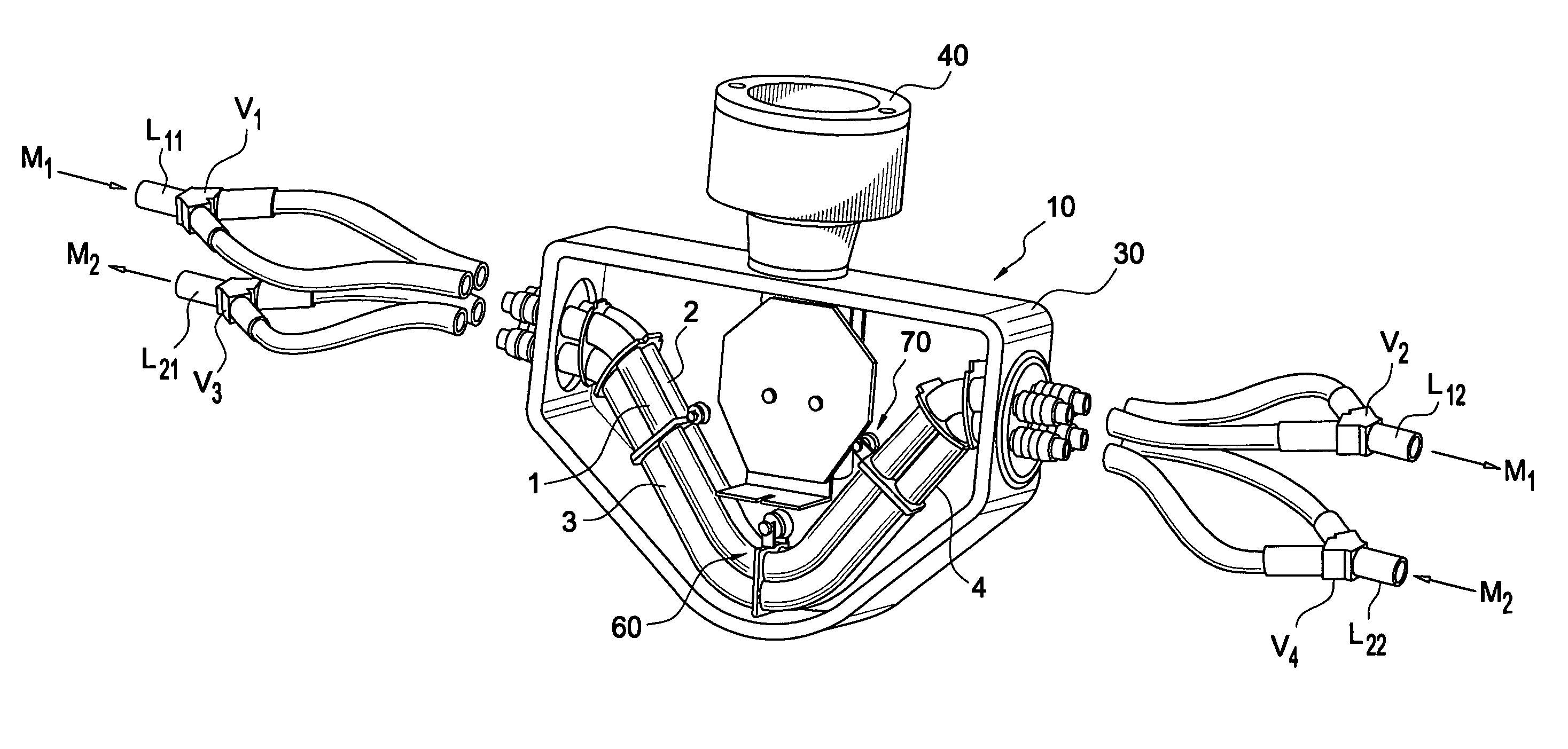
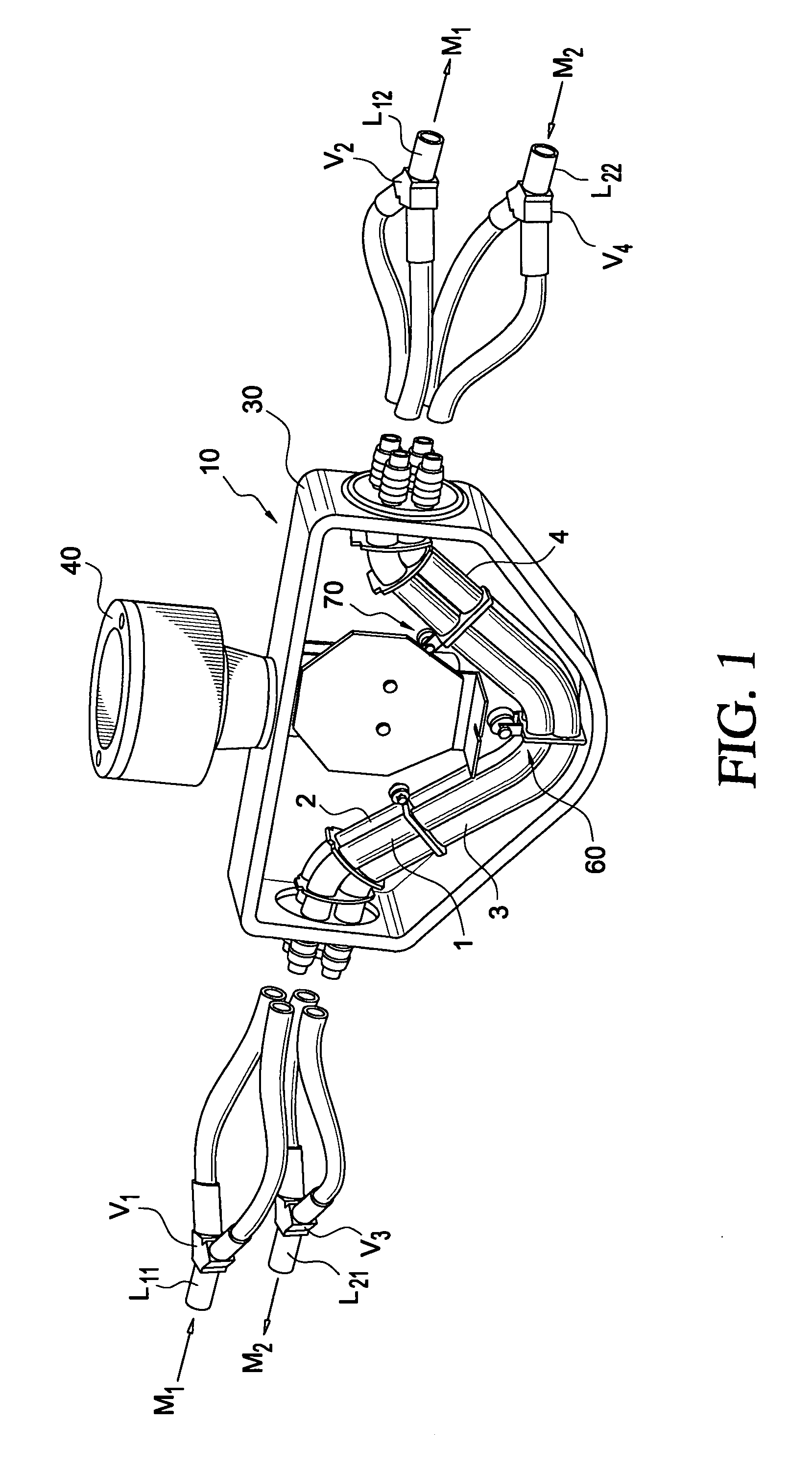
[0025]In the measurement pickup of the invention, the first in- / outlet end of each of the first and second measuring tubes is connected during operation with a first distributor element and the second in- / outlet end of each of the first and second measuring tubes is connected with a second distributor element. In the same way, also the first in- / outlet end of each of the third and fourth measuring tubes is connected during operation with a third distributor element, and the second in- / outlet end of each of the third and fourth measuring tubes is connected during operation with a fourth distributor element. Beyond this, the first distributor element is connected to a line segment of the first medium-line conveying a medium to the measurement pickup, and the second distributor element is connected to a line segment of the first medium-line conveying a medium away from the measurement pickup, and the third distributor element is connected to a line segment of the second medium-line con...

second embodiment

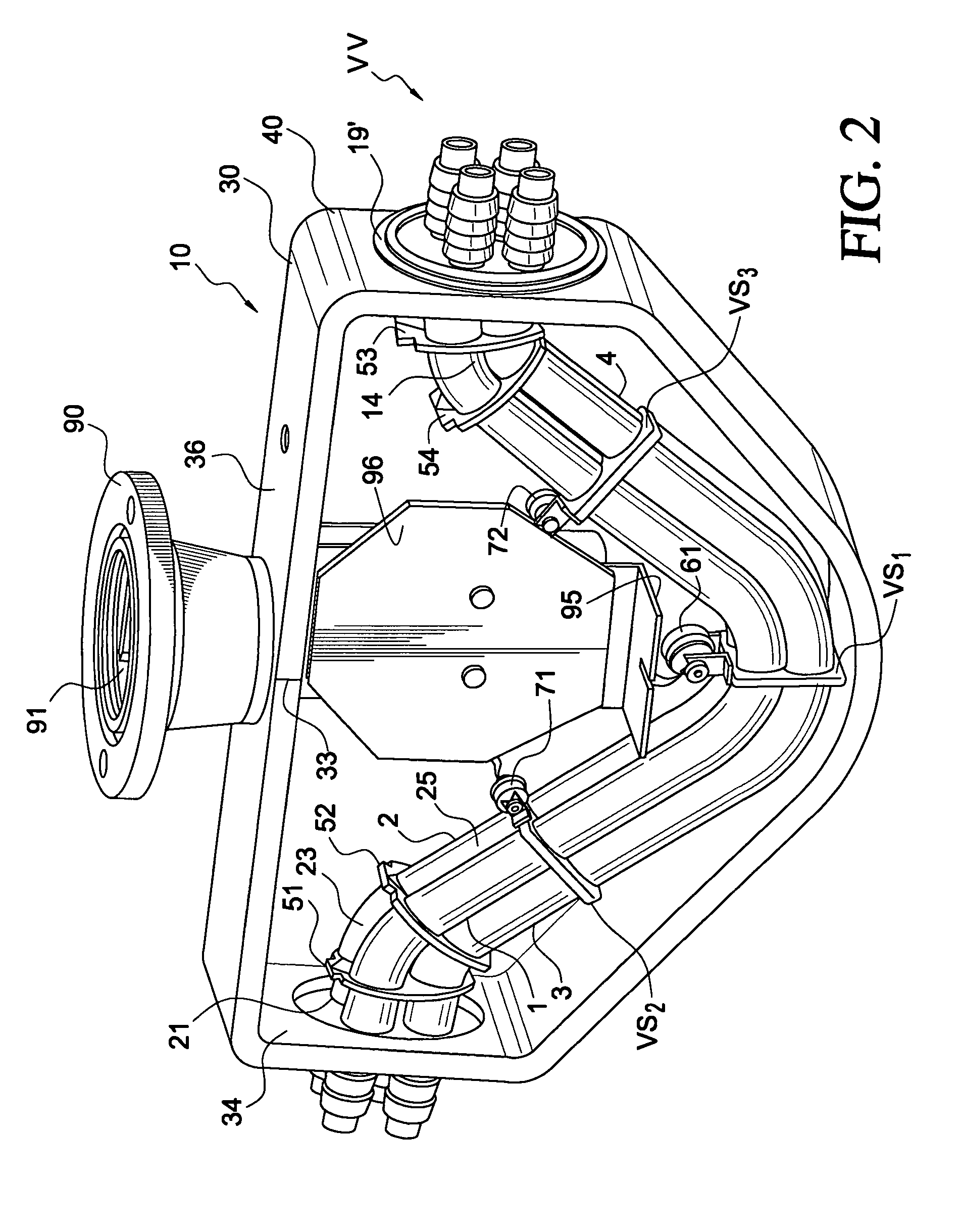
[0026]In the measurement pickup of the invention, the exciter mechanism includes an, especially differentially acting, electrodynamic, oscillation exciter, which acts on the measuring tubes via an exciter coil essentially rigidly coupled with the first and / or the third measuring tube(s) and a plunger armature plunging into these coils and essentially rigidly coupled with the second and / or the fourth measuring tube(s).

third embodiment

[0027]In the measurement pickup of the invention, the oscillation exciter is located above a common, local center of gravity of all four measuring tubes, which lies in an imaginary, cross-sectional plane passing through the location of installation of the oscillation exciter.


PUM


Abstract

A measurement pickup includes at least four measuring tubes for conveying media to be measured. Each measuring tube has a first in- / outlet end and a second in- / outlet end. During operation, the measuring tubes vibrate, at least at times, especially simultaneously. The measurement pickup further includes an electromechanical exciter mechanism causing the measuring tube to vibrate, as well as a sensor arrangement reacting at least to local vibrations of the measuring tubes for producing at least one measurement signal influenced by vibrations of the measuring tubes. Of the at least four measuring tubes, two measuring tubes are, at least at times, inserted into the course of a first medium-line such that each of these two measuring tubes simultaneously conveys, in each case, a partial volume of a medium flowing through the first medium line, and two other measuring tubes of the at least four measuring tubes are, at least at times, inserted into the course of a second medium line such that each of these two measuring tubes simultaneous conveys, in each case, a partial volume of a second medium flowing through the second medium line. The measurement pickup can thus, on the one hand, have two media flowing through it, which differ measurably from one another in at least one physical property, for example mass flow rate, medium density and / or medium temperature, while having, on the other hand, despite the different media, a good zero-point stability.

Description

[0001]This application claims the benefit of provisional application No. 60 / 590,902 filed on Jul. 26, 2004.FIELD OF THE INVENTION[0002]The invention relates to a measurement pickup for measuring media flowing in two, especially separate, lines, as well as to an inline measuring device having such a measurement pickup.BACKGROUND OF THE INVENTION[0003]For measuring, or registering, a process variable of media flowing in lines, especially pipelines, especially for registering flow-dynamic and / or Theological, measured variables, often such inline measuring devices are applied, which utilize a vibration-type, i.e. vibratory, measurement pickup inserted into the course of the medium-conveying pipe, tube or hose line, and a measuring and operating circuit connected thereto, to cause, in the medium flowing through the pickup during operation, reaction forces, such as e.g. Coriolis forces corresponding to the mass flow rate, inertial forces corresponding to the density or frictional forces c...

Claims


Application Information

Patent Timeline
Patent Type & Authority Patents(United States)
IPC IPC(8): G01F1/84
CPCG01F1/8409G01F1/8413G01F1/8422G01F1/8468G01F1/8477G01F1/8495G01F15/02
Inventor BITTO, ENNIOBERNHARD, HOLGER
Owner ENDRESS HAUSER FLOWTEC AG
Why Eureka
Try Eureka