Control system for architectural coverings with reversible drive and single operating element

a control system and control system technology, applied in the direction of curtain suspension devices, shutters/movable grilles, door/window protective devices, etc., can solve the problems of long operating element with which to operate the system, especially confusing, and long operating element length

Active Publication Date: 2006-10-31
HUNTER DOUGLAS INC
View PDF47 Cites 53 Cited by
  • Summary
  • Abstract
  • Description
  • Claims
  • Application Information

AI Technical Summary

Benefits of technology

[0010]In yet another form of the present invention, the input assembly includes a single operating element and is operative to convert linear motion of the operating element into rotational motion of a first motion transfer element. The transmission is operative to translate rotation of the first motion transfer element in the first direction into rotation of a second motion transfer element though a planetary gear set configured to selectively operate in a first configuration and a second configuration. The output assembly is operatively engaged with the second motion transfer element to rotate the head roller. The first configuration provides a first mechanical advantage and causes the second motion transfer element to rotate at a first speed. The second configuration provides a second mechanical advantage and causes the second motion transfer element to rotate at a second speed.

Problems solved by technology

This can be especially confusing if the operating elements are tangled.
Inherent in the loop operating element system is the problem of having a very long operating element with which to operate the system.
A greater length of the operating element or the use of a looped cord present a strangulation hazard to children who may become entangled in the operating element.

Method used


Image

  • Control system for architectural coverings with reversible drive and single operating element
  • Control system for architectural coverings with reversible drive and single operating element
  • Control system for architectural coverings with reversible drive and single operating element

Examples


second embodiment

[0165

[0166]Control System Overview

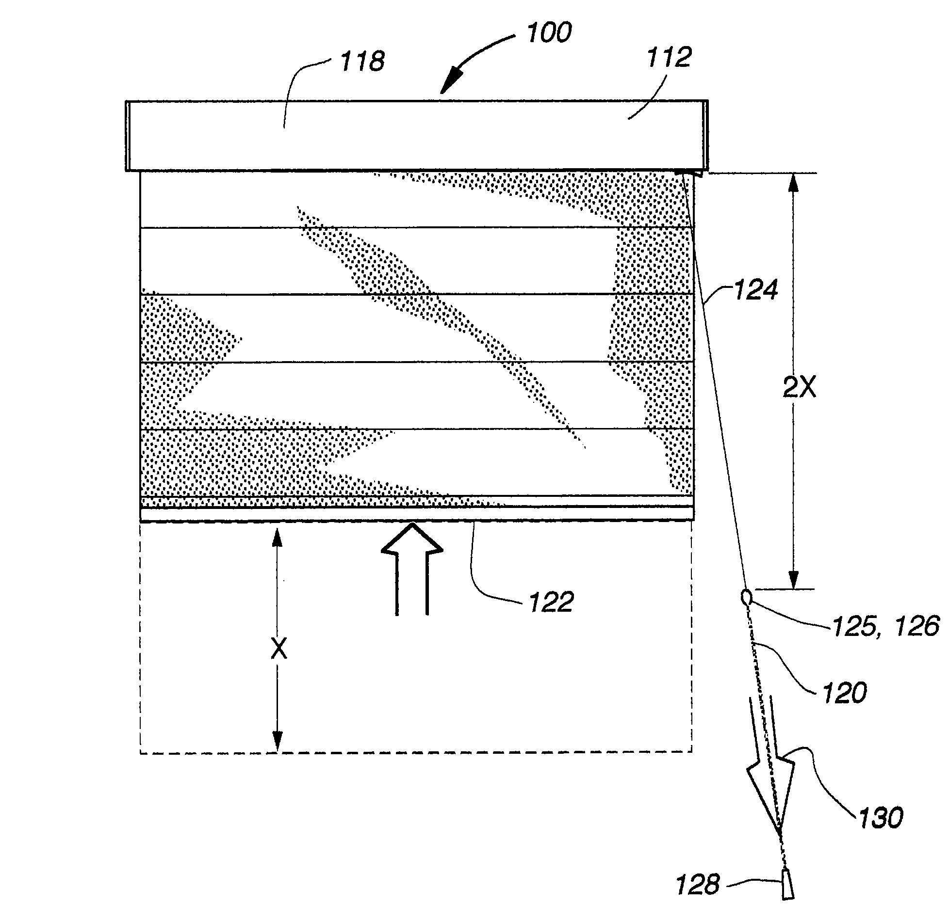
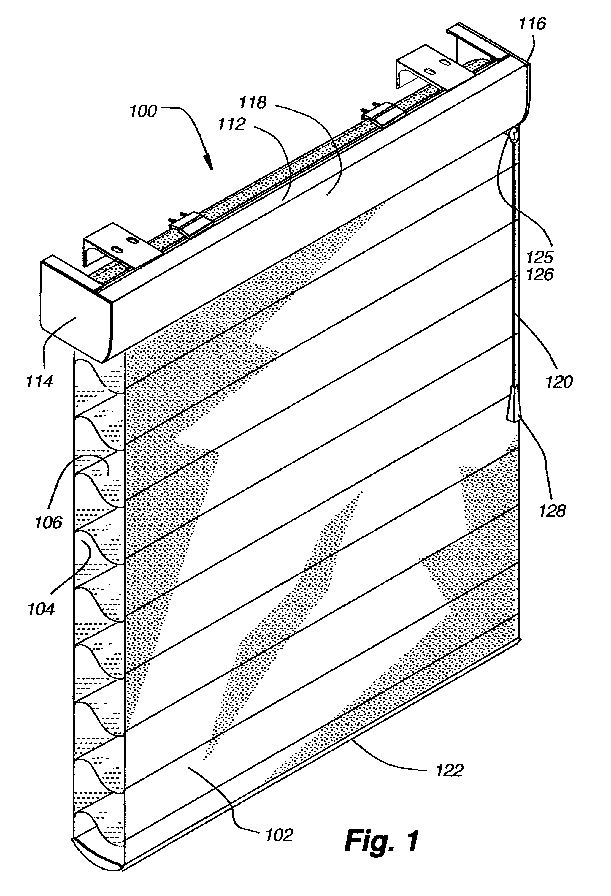
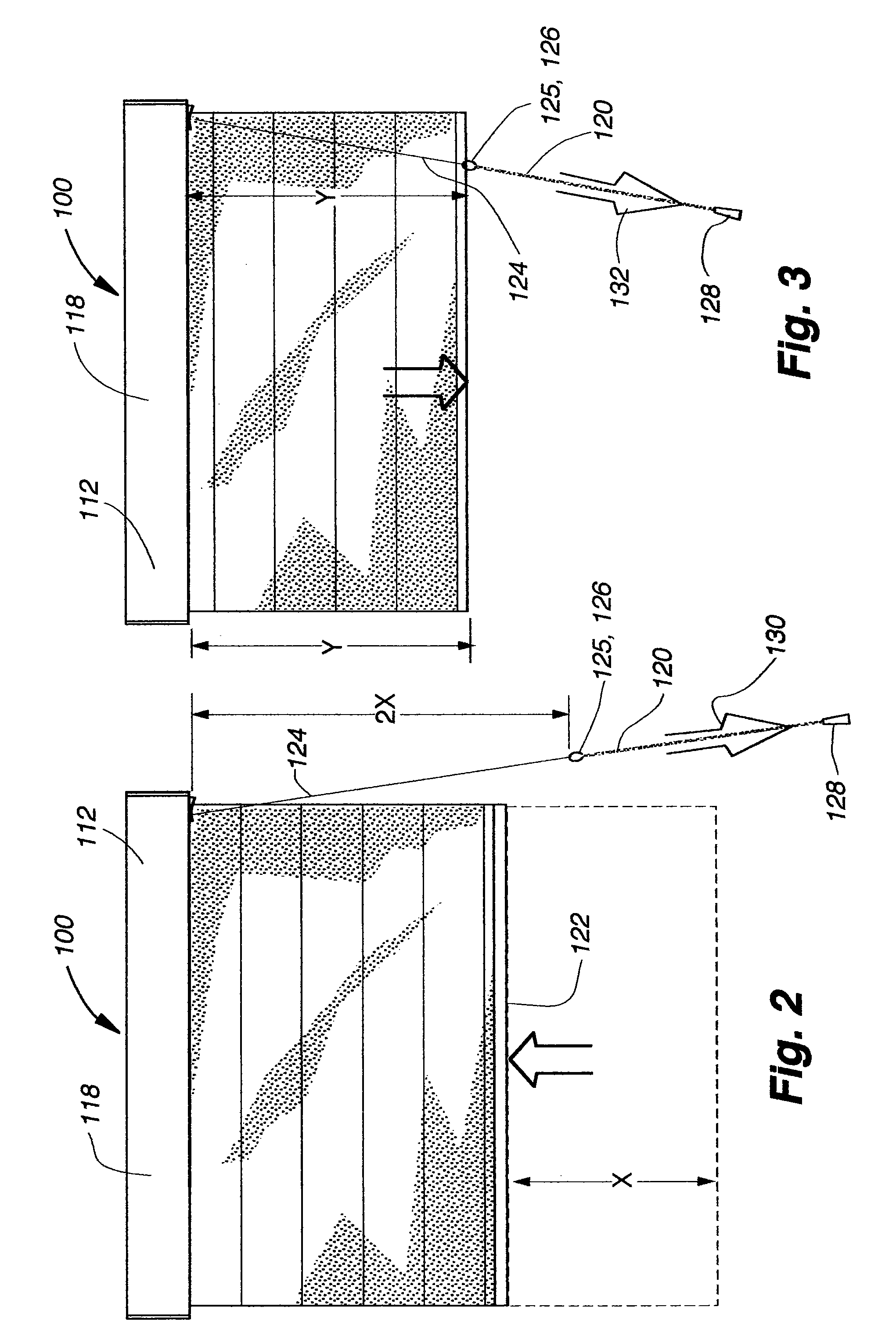
[0167]A second embodiment of the present invention is illustrated in FIGS. 8–15F2. The second embodiment of the control system 110′ provides the same functionality as the first embodiment 110 described above in that the control system 110′ allows a user to raise and lower the covering 100 by pulling on the pull cord 120 in either the upward operating pull direction 130 or the downward operating pull direction 132. The operating cord 124 of the second embodiment may also utilize the tassel 128 and stopper or coupler 125 described above. The second embodiment also provides for automatic retraction of the operating cord into the head rail assembly 112′ along with the braking system to hold the covering 100 in any selected position.

[0168]Similar to the first embodiment described above, the control system 110′ of the second embodiment includes an input assembly 174′, a transmission 176′, and an output assembly 178′ cooperatively engaging to convert linea...

third embodiment

[0217

[0218]Control System Overview

[0219]A third embodiment of the present invention is illustrated in FIGS. 16–21. The third embodiment of the control system 110″ provides the same functionality as the first and second embodiments described above in that the control system allows a user to raise and lower the covering 100 by repeatedly pulling downwardly on the pull cord 120. Unlike the first and second embodiments, a user of the third embodiment cannot change the direction in which the head roller 108 rotates by altering the direction in which the pull cord 120 is pulled. Instead, the user of the third embodiment manually actuates a trigger 530 on a control arm 532 to change the direction in which the head roller 108 rotates. The operating cord of the third embodiment may also utilize the tassel 128 and stopper or coupler 125 described above. The third embodiment also provides for automatic retraction of the operating cord into the head rail assembly 112″ along with the braking sys...


PUM


Abstract

The present invention provides for retractable coverings for architectural openings utilizing a control system having a single operating element allowing a user to move a retractable covering between extended and retracted positions by imparting a repetitive motion to the operating element. The control system may include an input assembly, a transmission, and an output assembly cooperatively engaging to convert linear movement of the operating element into rotational movement of a head roller in the required direction to provide movement of the covering in the desired direction and distance. The input assembly may convert linear movement of the operating element into rotational movement imparted to the transmission. The input assembly may also engage the transmission to effect the direction of rotational output from the transmission. The transmission imparts rotational movement to the output assembly, which interfaces with the head roller to rotate the head roller and to provide a braking feature.

Description

CROSS-REFERENCE TO RELATED APPLICATIONS[0001]This application claims priority to U.S. Provisional Application No. 60 / 452,222, filed Mar. 4, 2003, hereby incorporated by reference in its entirety as though fully set forth herein.BACKGROUND OF THE INVENTION[0002]a. Field of the Invention[0003]This invention relates to retractable coverings for architectural openings, and more particularly, an operating system for controlling retractable coverings for architectural openings using a single operating element.[0004]b. Background Art[0005]Operating systems utilized in window coverings for architectural openings, such as shade and blind assemblies are commonly used. Conventional shade and blind assemblies typically comprise a head rail, bottom rail, and slats or a covering disposed therebetween. Generally, a control system for raising and lowering such blinds or shades are installed in the head rail and may include an operating element, such as a cord, for lowering or raising the blinds or ...

Claims


Application Information

Patent Timeline
Patent Type & Authority Patents(United States)
IPC IPC(8): A47G5/02E06B9/262E06B9/322E06B9/34E06B9/42E06B9/68
CPCE06B9/262E06B9/322E06B9/34E06B9/42E06B9/68E06B2009/2627
Inventor SMITH, STEPHEN P.COLSON, WENDELL B.MILLER, JAMES L.
Owner HUNTER DOUGLAS INC
Why Eureka
Try Eureka