Apparatus and method for reverse tunneling a multi-lumen catheter in a patient

a multi-lumen catheter and reverse tunneling technology, applied in the field of medical instruments, can solve the problems of ineffective dialysis treatment, lack of accuracy of catheter tip placement in double-lumen catheters, and present certain deficiencies

Inactive Publication Date: 2006-10-31
TELEFLEX LIFE SCI LTD +1
View PDF79 Cites 167 Cited by
  • Summary
  • Abstract
  • Description
  • Claims
  • Application Information

AI Technical Summary

Benefits of technology

[0006]An apparatus and method are provided for reverse tunneling a distal portion of a multilumen catheter tube. The apparatus and method are particularly adapted for use with a multilumen catheter having a selectively detachable hub assembly like that disclosed in applicant's pending application Ser. No. 09 / 769,052, filed Jan. 24, 2001, and pending application Ser. No. 10 / 086,033, the contents of which are incorporated herein by reference. The apparatus and method permit the proximal tips of a multilumen catheter to be accurately positioned within a patient's vein prior to subcutaneous tunneling of the distal portion of the catheter tube, and permit the distal end of the catheter tube to be subcutaneously tunneled in the patient prior to attachment to a hub assembly.

Problems solved by technology

Both types, however, present certain deficiencies.
While double lumen catheters (e.g., U.S. Pat. No. 4,895,561) allow for a single venous insertion of the catheter into the desired vein, double lumen catheters typically do not provide for accuracy of catheter tip placement.
Non-optimal tip position may significantly lower flow values, resulting in less effective dialysis treatment.
The initial estimate and subsequent forward tunneling may result in less than optimal tip placement.
Deficiencies, however, exist in this method of catheterization as well.
One problem associated with this method is that it requires two separate venous insertions, namely, two tunnels and two of each accessory instruments used for the procedure.

Method used


Image

  • Apparatus and method for reverse tunneling a multi-lumen catheter in a patient
  • Apparatus and method for reverse tunneling a multi-lumen catheter in a patient
  • Apparatus and method for reverse tunneling a multi-lumen catheter in a patient

Examples


Embodiment Construction

[0020]For the purposes of the following description and the claims appended hereto, the relative term “proximal” refers to those portions of a catheter and those portions of components of the catheter which are nearest the insertion end of the catheter, that is, the end of the catheter that is inserted into an area of a patient's body being catheterized, such as a blood vessel. Conversely, the relative term “distal” refers to those portions of a catheter and those portions of components of the catheter which are farthest from the insertion end of the catheter.

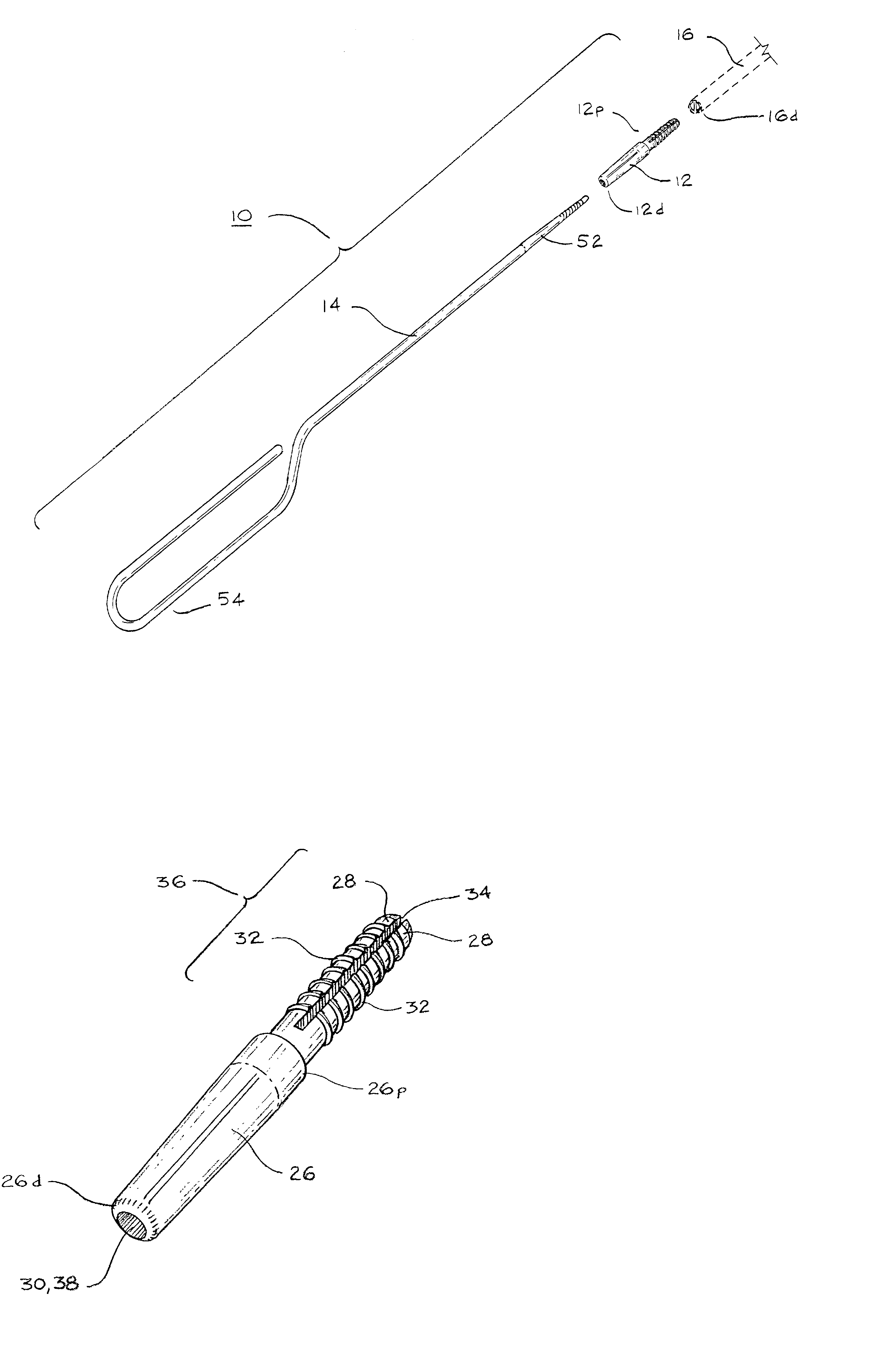
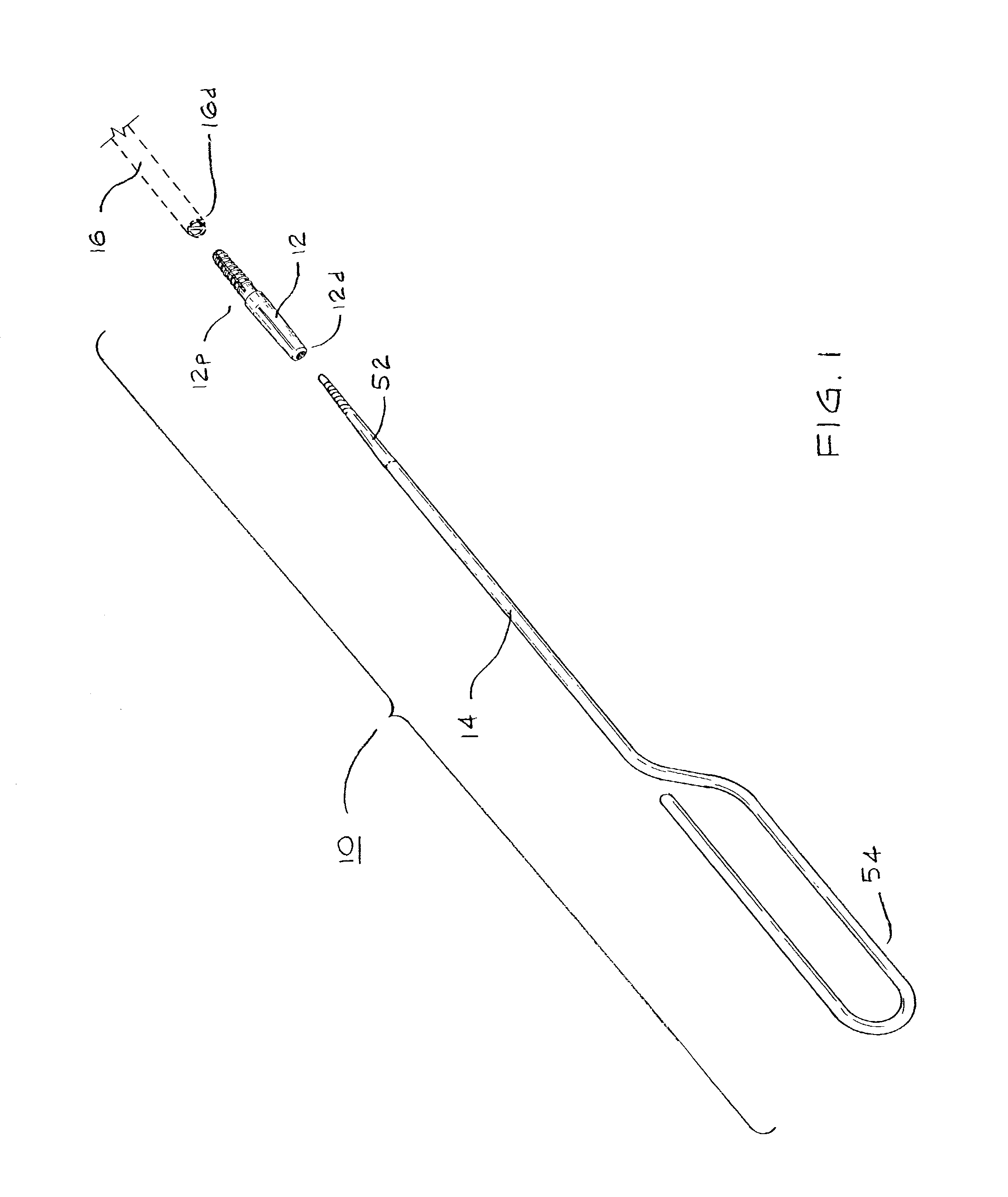
[0021]As shown the Figures, an apparatus 10 is provided for reverse tunneling a multilumen catheter 16 in a patient. In the embodiment shown in FIG. 1, the apparatus 10 includes a connector 12 and a trocar 14. The connector 12 includes a proximal end 12p that is configured for selective connection to the distal end 16d of a multilumen catheter tube 16. The connector 12 also includes a distal end 12d that is configured for selec...


PUM


Abstract

An apparatus and method for tunneling a distal portion of a multilumen catheter tube in a patient is disclosed. The apparatus includes a connector having a distal end and a proximal end. The proximal end includes a first coupling portion for selective connection to a distal end of the multilumen catheter tube, and the distal end of the connector includes a second coupling portion. A trocar is provided having a first end and a second end. The second end of the trocar is configured for selective connection to the coupling portion of the connector. The connector and the second end of trocar are configured such that they are substantially coaxially aligned with the multilumen catheter tube when the first coupling portion of the connector is selectively joined with the distal end of the multilumen catheter tube and the second end of the trocar is selectively engaged with the second coupling portion of the connector. A method of reverse tunneling a multilumen catheter tube using such an apparatus is also disclosed.

Description

FIELD OF THE INVENTION[0001]The present invention relates generally to medical instrumentation and more specifically to an apparatus and method for subcutaneously tunneling a multilumen catheter in a patient.BACKGROUND[0002]Catheters, generally, are hollow, flexible tubes for insertion into a body cavity, duct, or vessel to allow the passage of fluids or distend a passageway. Catheters are often used for temporary or long-term dialysis treatment. Dialysis treatment provides for blood to be withdrawn from the patient, purified, and then returned to the patient. Thus, in dialysis treatment, catheters are used to allow passage of a patient's blood into and out of the patient's body. For optimal performance during dialysis treatment, the catheter tips, both in-flow and out-flow, should be placed in close proximity to the heart. Typically, medical personnel use either a double lumen catheter or two single lumen catheters. Both types, however, present certain deficiencies.[0003]While doub...

Claims


Application Information

Patent Timeline
Patent Type & Authority Patents(United States)
IPC IPC(8): A61M31/00A61M25/16B25G3/28F16B37/04F16D1/00A61B17/34A61MA61M25/00A61M25/14
CPCA61B17/3415A61M25/0194Y10T403/7024Y10T403/5773
Inventor WILSON, JON S.CASSIDY, KENNETH T.MARTEL, MARK C.
Owner TELEFLEX LIFE SCI LTD
Why Eureka
Try Eureka