
Object figuring device

a technology of object figuring and object, which is applied in the field of object figuring devices, can solve the problems of troublesome optical phenomena in sensory perception, the arrangement described in this reference is not suitable for spot scanning, and a portion of radiated energy is availabl

Inactive Publication Date: 2006-10-31
CARL ZEISS MEDITEC AG
View PDF37 Cites 47 Cited by
  • Summary
  • Abstract
  • Description
  • Claims
  • Application Information

AI Technical Summary

Benefits of technology

[0013]The primary object of the invention is to develop further a device of the type described above in such a way that sculpting or shaping can be carried out quickly and effectively and remainder of bothersome microstructures on the surface of the object is avoided.

Problems solved by technology

Steplike irregularities of this kind on the cornea lead to troublesome optical phenomena in sensory perception.
It is disadvantageous that the arrangement described in this reference is not suitable for spot scanning, i.e., it is possible to treat only relatively large surface portions (spots) in their entirety.
However, only a portion of the radiated energy is available in the fundamental mode TEM00, this portion not being sufficient, for example, for corneal ablation.

Method used


Image

  • Object figuring device
  • Object figuring device
  • Object figuring device

Examples


Embodiment Construction

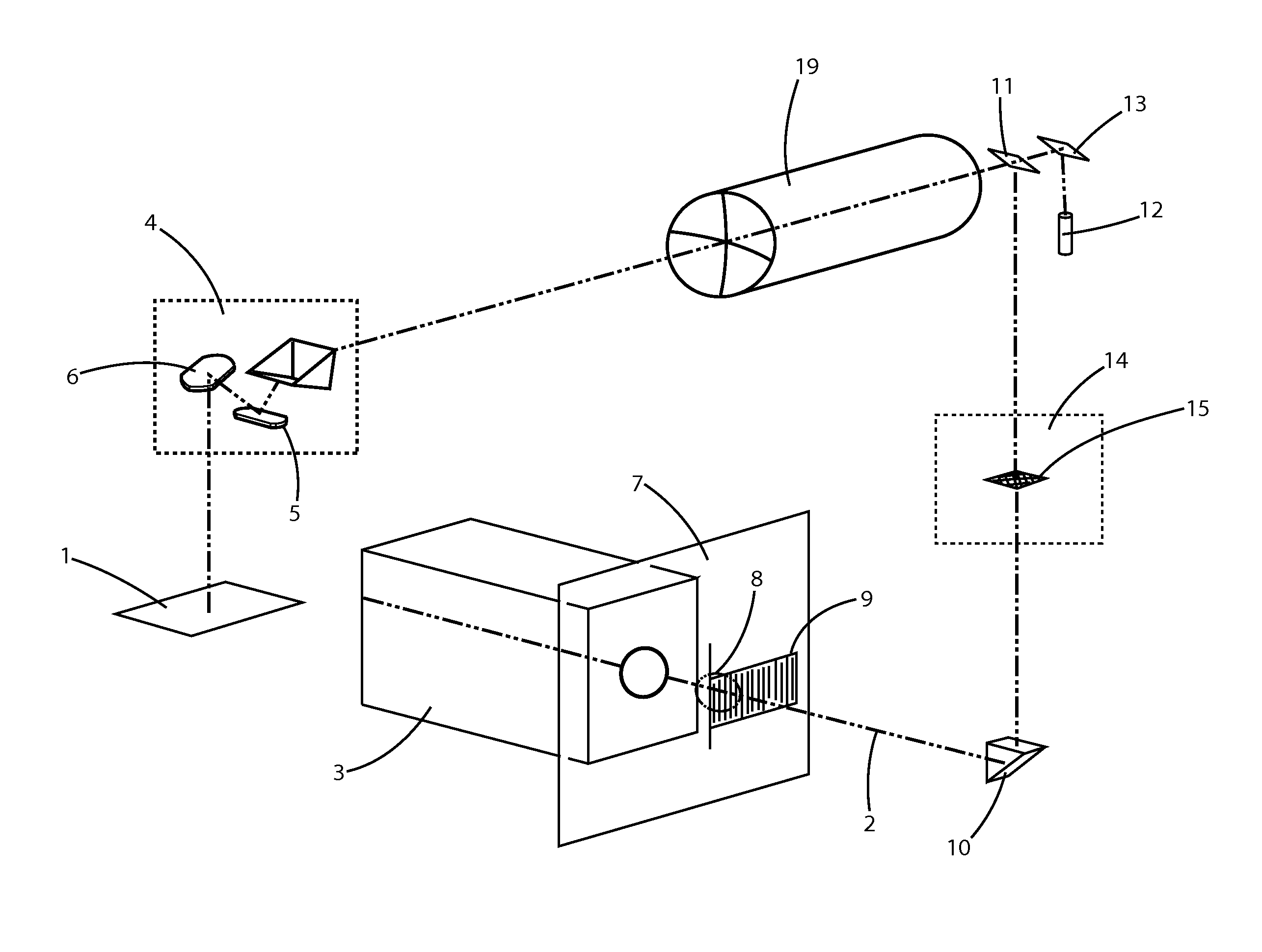
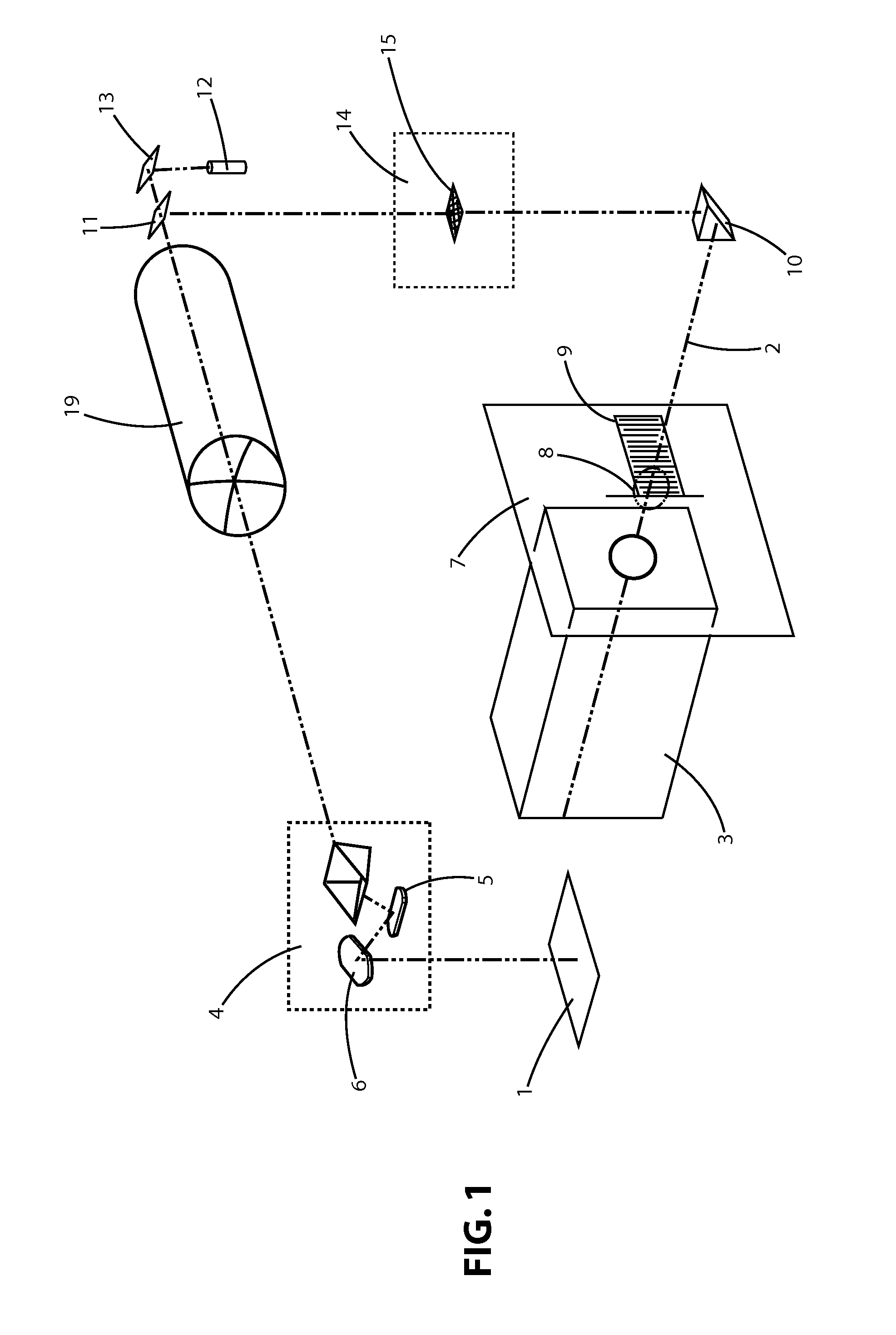
[0046]FIG. 1 shows a device for shaping an object 1 by means of a pulsed laser beam 2 emanating from an excimer laser 3. The laser beam 2 is guided over the surface of the object 1 by means of a deflecting device 4 in which an X-scanner mirror 5 and a Y-scanner mirror 6 are provided. The energy entering the surface of the object 1 through the laser beam 2 causes an ablation of material. The object 1 can be, for example, a human eye whose cornea is being treated by ophthalmologic shaping in order to correct deficient vision. However, the device according to the invention can also be applied, for example, for shaping artificial lenses which are provided for the correction of deficient vision.

[0047]The laser beam 2 emanating from the excimer laser 3 is guided through a containment wall 7 with windows 8 and attains the surface of the object 1 via a variable attenuator 9, a deflecting prism 10, an optical splitter 11 and via the deflecting device 4.

[0048]For the purpose of visual observa...


PUM

PropertyMeasurementUnit
Fractionaaaaaaaaaa
Angleaaaaaaaaaa
Structureaaaaaaaaaa

Abstract

A device for figuring objects by means of material erosion of the surface thereof, comprising a pulsed laser beam and a deflection device through which the laser beam is directed at the object surface and via which the object surface is guided. The invention is suitable for figuring natural optical lenses made from a biological substance or artificial optical lenses. The inventive device is provided with an optical device to modify the distribution of the radiation intensity inside the laser beam cross section. The radiation intensity, once the laser beam has passed through the optical device, has a bell-shaped or Gaussian-like distribution in at least one cross sectional direction through the laser beam.

Description

BACKGROUND OF THE INVENTION[0001]a) Field of the Invention[0002]The invention relates to a device for sculpting or shaping objects by removal of material from the surface thereof with a pulsed laser beam and a deflecting device through which the laser beam is guided over the surface of the object. It is advantageously suited for shaping natural optical lenses of biological substance or for shaping artificial optical lenses.[0003]b) Description of the Related Art[0004]Known prior art includes various devices and methods which are suitable for removal of material from the surface of an object by means of laser radiation and accordingly for shaping these objects, for example, for ablating tissue in the corneal region of the eye and for ophthalmologic shaping of eye lenses.[0005]The first publications on influencing visual deficiency of the human eye by changing the convexity or concavity of the cornea date from around 1983 to 1985. Comparatively more corneal tissue must be removed in t...

Claims


Application Information

Patent Timeline
IPC IPC(8): A61B18/18A61B18/20B23K26/06B23K26/073
CPCB23K26/073
Inventor GODER, CLAUSHOLLERBACH, THOMASKUEHNERT, JUERGENSCHROEDER, ECKHARD
Owner CARL ZEISS MEDITEC AG
Learn More