
Cell comprising a power-generating element fastened by sheets

a power-generating element and cell technology, applied in the field of cells, can solve the problems of small short circuit between the positive and negative electrodes, damage to the separation device, and material applied to the inner electrode may fall off, so as to prevent swelling, reduce cell capacity and service life of the cell.

Inactive Publication Date: 2006-10-31
GS YUASA INT LTD
View PDF13 Cites 27 Cited by
  • Summary
  • Abstract
  • Description
  • Claims
  • Application Information

AI Technical Summary

Benefits of technology

[0017]Therefore, an object of the present invention is to provide a cell in which the interelectrode distance between the positive and negative electrodes is maintained at a constant value such that the cell can be prevented from swelling, in which the electrolyte can be maintained in the separators homogeneously so that the variations in the charge and discharge characteristics between the power-generating elements or between the cells and the falling-off of the active material and breakage of the substrates can be prevented so that reduction in the cell capacity and service life of the cell is restrained.
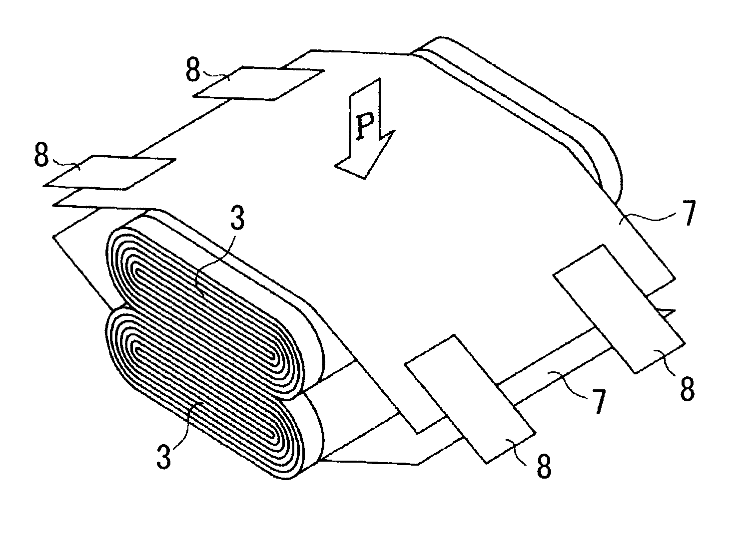
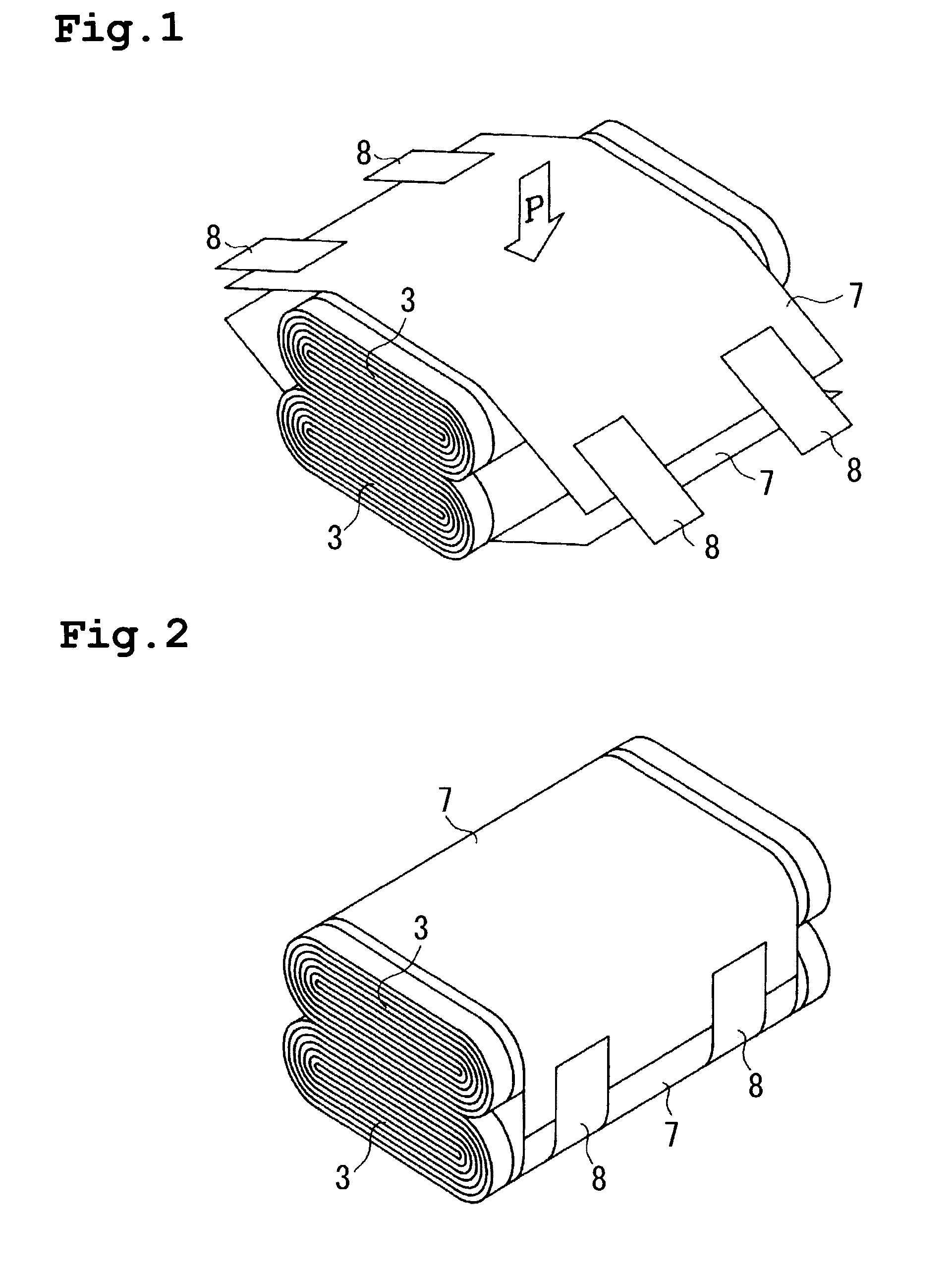
[0019]A plurality of the power-generating elements are superposed on each other or one another and are banded by the sheet member covering them. Accordingly, since the peripheral flat portions of the power-generating elements are pressed against each other or one another, the peripheral flat portions can be restrained from expansion. Consequently, an increase in the interelectrode distance between the positive and negative electrodes can be prevented in each power-generating element, deformation of each power-generating element into the cylindrical shape can be prevented, and the cell case can be prevented from expansion.
[0021]The substrate edges are bent inside so as to adhere closely to each other, whereupon the cell can be prevented from deformation. Further, the substrate edges can be prevented from damage when the power-generating elements are housed into the cell case. Additionally, the substrates and active materials on the positive and negative electrodes can be prevented from breakage and falling-off.

Problems solved by technology

Additionally, even where the separator is wound around an outermost peripheral face of the power-generating element 3, the separator may be damaged when the power-generating element 3 is housed into the case, whereupon an active material applied to inner electrodes may fall off.
Furthermore, pieces of the active material that have fallen off move in the cell case 1 during use of the cell, resulting in a tiny short circuit between the positive and negative electrodes.
This poses a problem.
In this case, too, broken pieces of the substrate and fallen pieces of the active substance may adhere to the positive or negative electrode, resulting in a tiny short circuit.
This adversely affects the charge and discharge characteristics of the cell, resulting in variations in the characteristics between the power-generating elements 3 and between the cells.
On the other hand, when the clamping force is excessively small, an interelectrode distance becomes unstable, whereupon the charge and discharge characteristics vary among power-generating elements and among cells.

Method used


Image

  • Cell comprising a power-generating element fastened by sheets
  • Cell comprising a power-generating element fastened by sheets
  • Cell comprising a power-generating element fastened by sheets

Examples


first embodiment

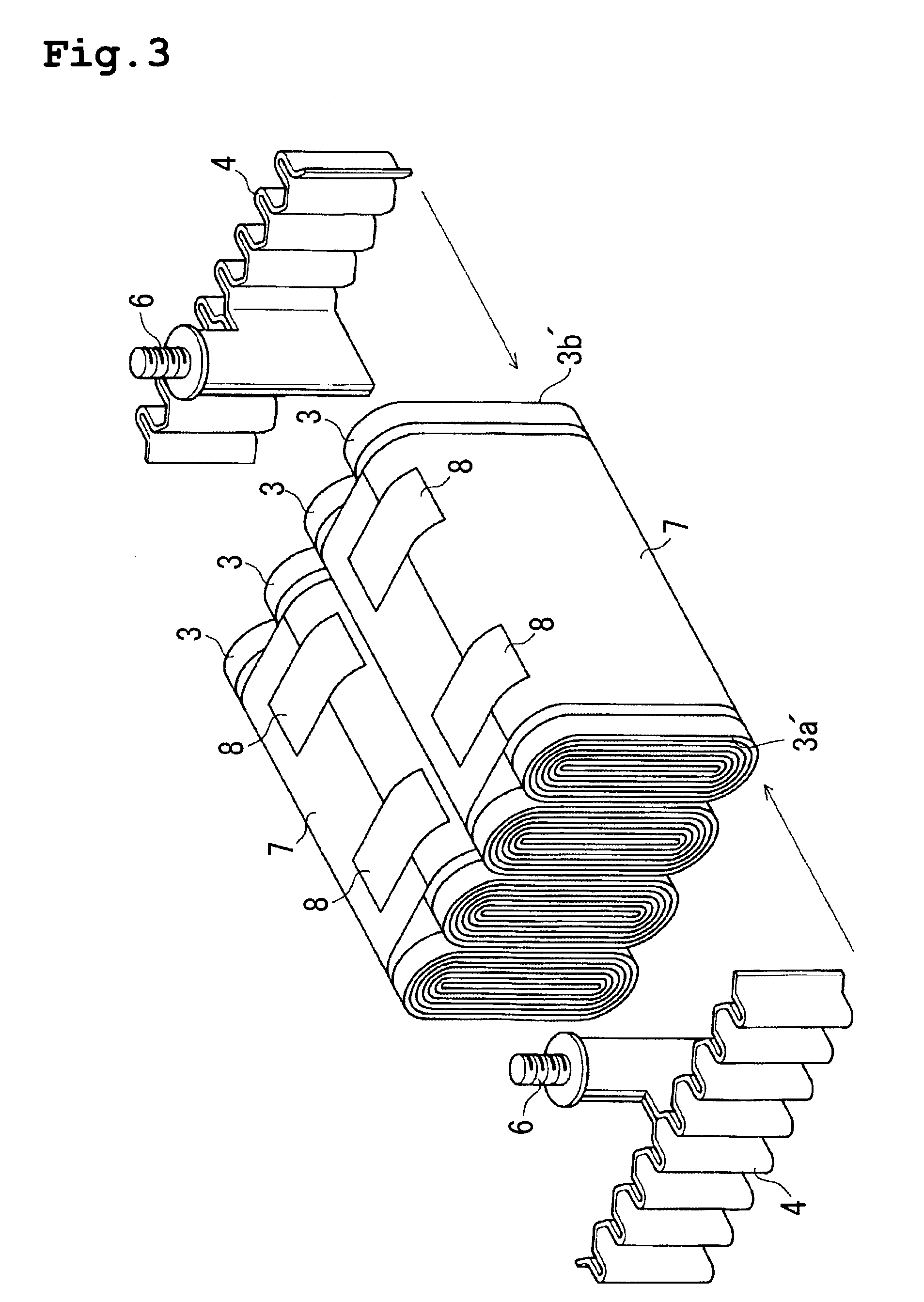
[0038]A first embodiment of the present invention will be described with reference to FIGS. 1 to 3. In the first embodiment, the present invention is applied to a large-scale nonaqueous electrolytic secondary cell. The cell comprises four generally elliptic cylindrical wound power-generating elements 3 as in the conventional cell shown in FIGS. 10 and 11. Each power-generating element 3 has a flat peripheral side face superposed on one of the adjacent element and is housed in a cell case 1. The power-generating elements 3 include positive electrodes 3a and negative electrodes 3b which are connected via current collectors 4 to positive terminals 6a and negative terminals 6b, respectively.

[0039]A strip-like positive electrode 3a and negative electrode 3b are wound into the shape of an elliptic cylinder with a separator 3c being interposed therebetween, as shown in FIG. 11. The positive electrode 3a includes a strip-like aluminum foil serving as a substrate. The aluminum foil has a sur...

second embodiment

[0049]FIGS. 4 to 8 illustrate a second embodiment of the present invention. In the second embodiment, the present invention is applied to a nonaqueous electrolytic secondary cell having a different current collecting structure from that in the first embodiment, and a metal foil of the electrode projecting from an end face of the power-generating element is bent at an arc portion.

[0050]FIGS. 4 and 5 illustrate a connecting structure for the power-generating element 3 and current collector 4. The nonaqueous electrolytic secondary cell includes a parallel connection of two elliptic cylindrical power-generating elements 3. Each power-generating element 3 comprises a horizontally disposed, generally trapezoidal collector body 4a and four generally comb-teeth-like slender connecting portions 4b that are diverged downward from a bottom side of the collector body 4a. Each connecting portion 4b includes a plurality of convex portions which are formed at predetermined intervals so as to protr...


PUM


Abstract

A cell such as a nonaqueous electrolytic secondary cell includes a plurality of power-generating elements which each include a strip-like positive electrode and a strip-like negative electrode that are both wound into an elliptic cylinder with a separator being interposed therebetween, where each power-generating element has a peripheral face including at least a flat portion. The cell also includes a cell case for housing the power-generating elements, where the cell case has an opening, and a cover hermetically sealing the opening of the cell case. The flat portion of each power-generating element is superposed on the flat portion of the adjacent power-generating element, and a sheet member is wound around peripheries of the superposed power-generating elements to fasten the power-generating elements such that the power-generating elements are integrated.

Description

BACKGROUND OF THE INVENTION[0001]1. Field of the Invention[0002]The present invention relates to a cell comprising a plurality of generally elliptic cylindrical wound generating elements, such as a nonaqueous electrolytic secondary cell.[0003]2. Description of the Related Art[0004]In conventional prismatic cells of large discharge capacity, e.g. a nonaqueous electrolytic secondary cell, a plurality of elliptic cylindrical wound power-generating elements are superposed and housed into a cell case. In the nonaqueous electrolytic secondary cell, as shown in FIG. 9, four elliptic cylindrical wound power-generating elements 3 have respective peripheral flat side faces superposed on one another and are housed into a cell case 1. FIG. 10 illustrates a connecting structure of the power-generating elements 3 and current collectors 4. The illustrated nonaqueous electrolytic secondary cell comprises four elliptic cylindrical wound power-generating elements 3 which are connected in parallel to ...

Claims


Application Information

Patent Timeline
IPC IPC(8): H01M2/02H01M4/64H01M6/00H01M6/10H01M6/42H01M10/04H01M10/38H01M50/147
CPCH01M2/145H01M2/263H01M6/42H01M10/04H01M10/0413H01M10/0463H01M2/04H01M2/16Y02E60/10H01M50/147Y02P70/50
Inventor MUNENAGA, NORIYOSHISHIMOZONO, TAKESHITASAI, HIROSHISUZUKI, ISAO
Owner GS YUASA INT LTD
Learn More