

Organic EL display device with plural electrode segments
- Summary
- Abstract
- Description
- Claims
- Application Information
AI Technical Summary
Benefits of technology
Problems solved by technology
Method used
Image

Examples
second embodiment
[0057]Next, referring to FIG. 5 and FIG. 6, a description will be given of an organic EL display device according to the present invention.
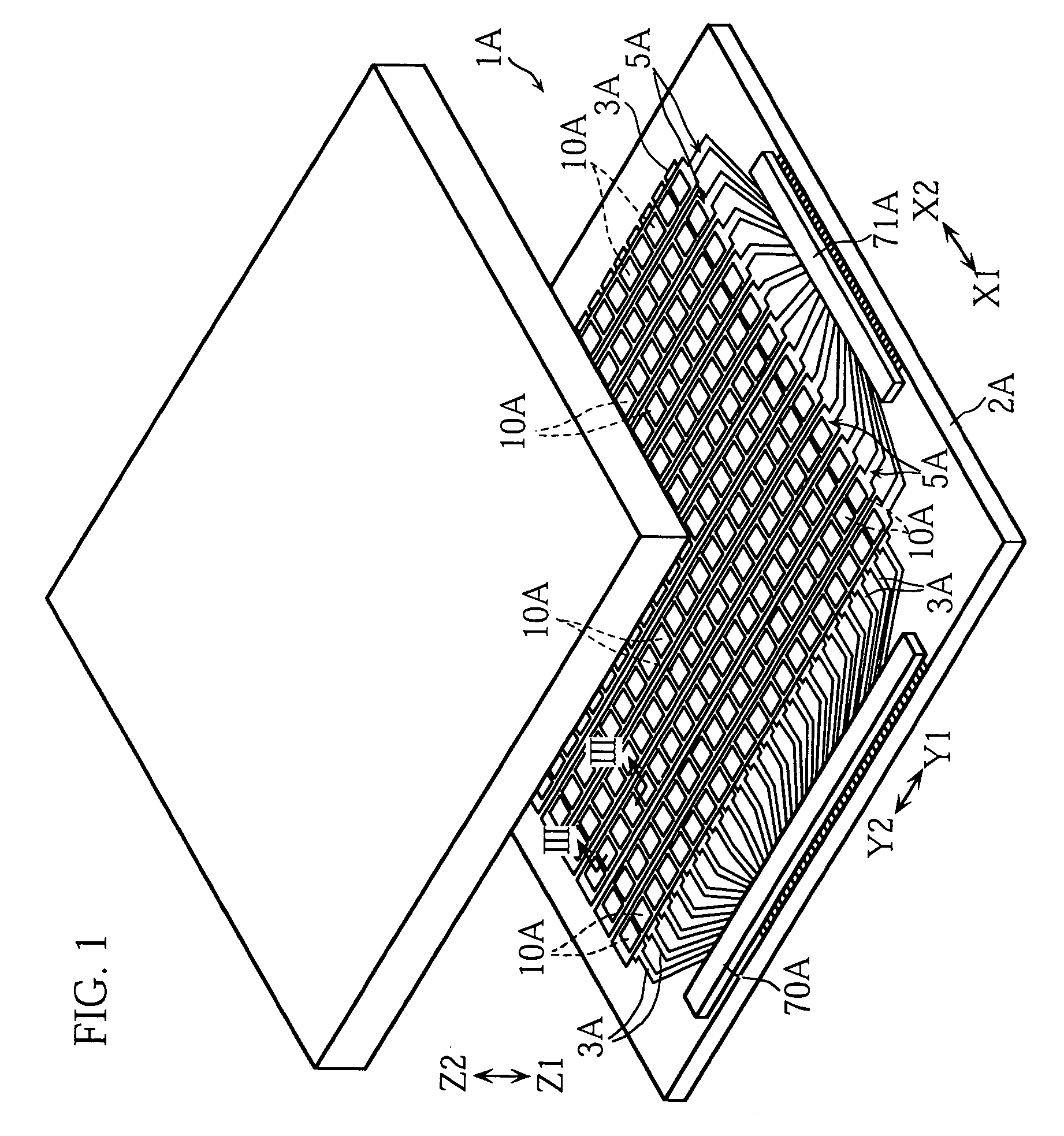
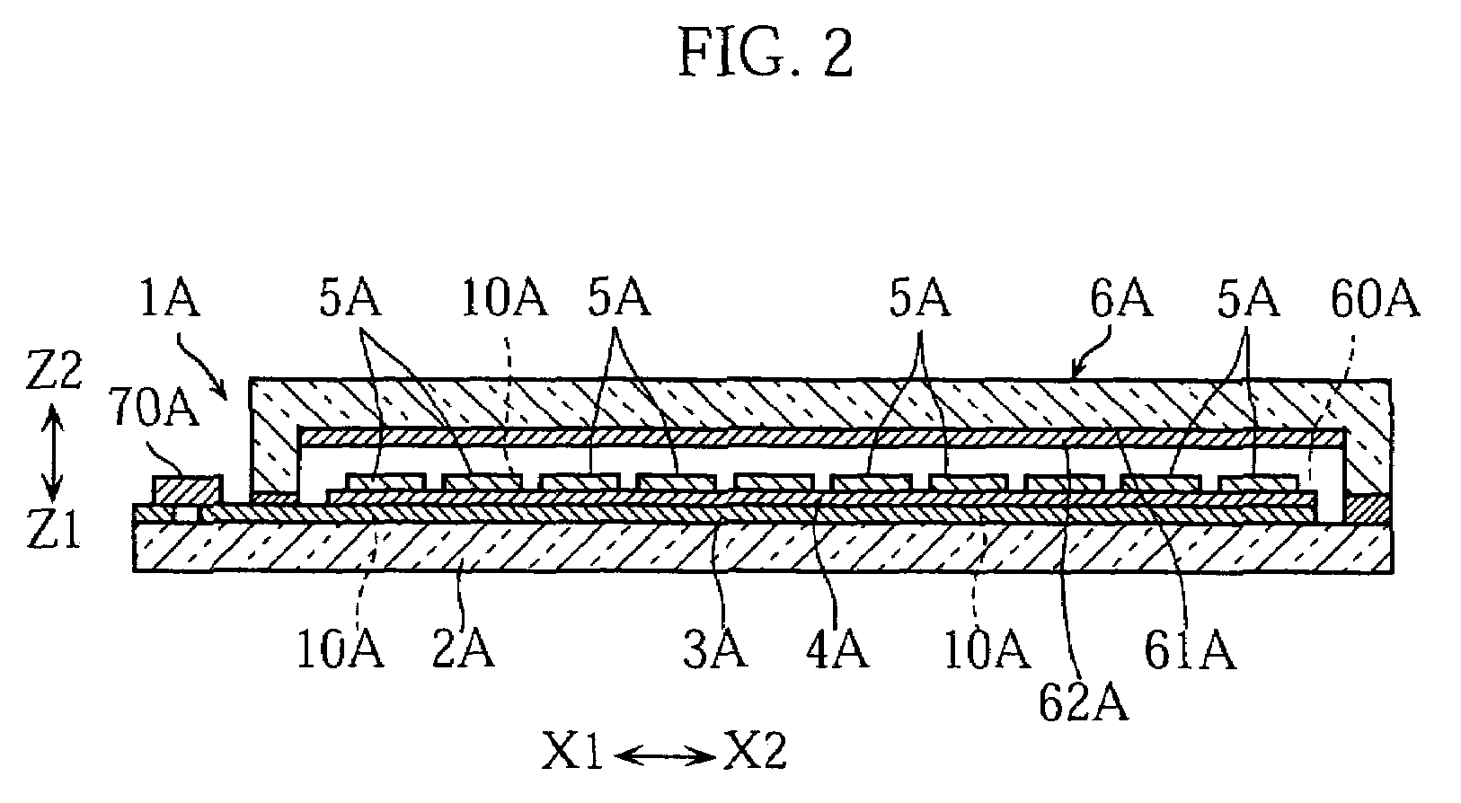
[0058]As with the organic EL display device 1A (see FIGS. 1–4) previously described, the organic EL display device 1B shown in FIG. 5 and FIG. 6 has a structure in which a plurality of display elements 10B are arranged in a matrix pattern. The display device is capable of displaying an image on its both surfaces by selectively actuating each display element 10B for light emission. The organic EL display device 1B includes a transparent substrate 2B, a plurality of anodes 3B, a plurality of organic laminates 4B, a plurality of cathodes 5B and a cover 6B.
first embodiment
[0059]Each of the cathodes 5B is provided on the substrate 2B in the form of a strip extending in an arrow Y1-Y2 direction and spaced from each other in an arrow X1-X2 direction. The cathodes 5B respectively include a plurality of cathode segments 13B and are made transparent. Between each two adjacent cathodes 5B, there is provided a separator 84B for electrically insulating the respective cathodes 5B. The cathodes 5B may be made of the same material by the same method as the anodes 3A of the organic EL display device 1A (see FIGS. 1–4) according to the
[0060]Each of the anodes 3B is provided in the form of a strip extending perpendicularly to the cathodes 5B in the arrow X1-X2 direction. Each of the anodes 3B is formed over the cathodes 5B via a separator 85B and includes a plurality of anode segments 11B. The anodes 3B are spaced from each other in the Y1-Y2 direction. The anodes 3B may be made of the same material as the cathodes 5A of the organic EL display device 1A (see FIGS. ...
PUM
 Abstract
Description
Claims
Application Information