Cylinder liner providing coolant shunt flow

a technology of cylinder liner and coolant, which is applied in the direction of cylinders, machines/engines, mechanical equipment, etc., can solve the problems of limited heat exchange area and high mechanical stress, limited heat exchange area of this cooling system, and high mechanical stress on the ridge points, so as to increase the total heat exchange area, increase the facial area, and increase the effect of heat exchange area

Inactive Publication Date: 2006-11-07
BUESCHER DEV
View PDF4 Cites 7 Cited by
  • Summary
  • Abstract
  • Description
  • Claims
  • Application Information

AI Technical Summary

Benefits of technology

[0009]According to the present invention, the new liner is provided with three annular cooling channels, each extending in axial length (i.e., in width) across substantially less than half the axial length (width) of the upper cylinder block engaging portion of the liner. The three cooling channels are partly defined by two ribs that are integral with the liner body and whose peaks are flat in profile. The channels are each generally rectilinear in cross section to increase facial area and thereby increase total heat exchange area. The array of cooling channels extends in axial length across a substantial majority, preferably 70% or more, of the axial...

Problems solved by technology

It is to be noted that the flow capacity of this cooling system is severely limited by the in-series (as distinguished from in-parallel) nature of the flow arrangement, the cross sectional flow area in the disclosed system approaching as little as a third of what it would be were the flow arrangement parallel in nature.
This arcuate and “pointy” design has disadvantages as compared t...

Method used


Image

  • Cylinder liner providing coolant shunt flow
  • Cylinder liner providing coolant shunt flow
  • Cylinder liner providing coolant shunt flow

Examples


Embodiment Construction

[0021]Liners are located at points of high wear in the engine, and are intended to be replaced from time to time with new or rebuilt liners, in that respect reconditioning the engine for further efficient operation

[0022]In order to provide a frame of reference for a more complete understanding of the present invention, a prior-art liner design and the operation of such liner in conjunction with an associated engine block will first be described in some detail. It will be understood that the engine block itself is generally intended to remain wholly or substantially unchanged in design after the liners are replaced, and this remains true in particular when the design of the replacement liner is changed from that of the original liner.

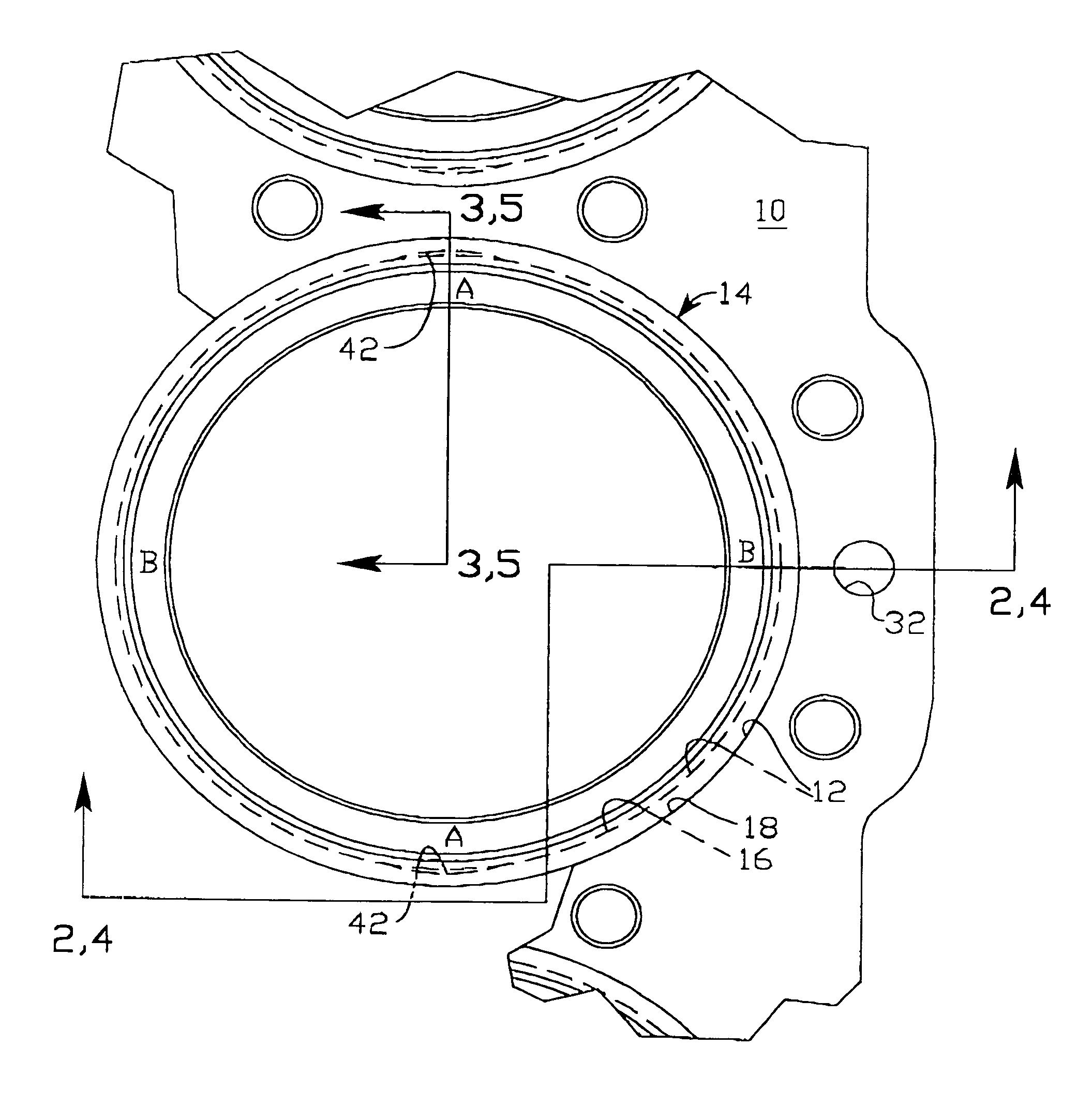
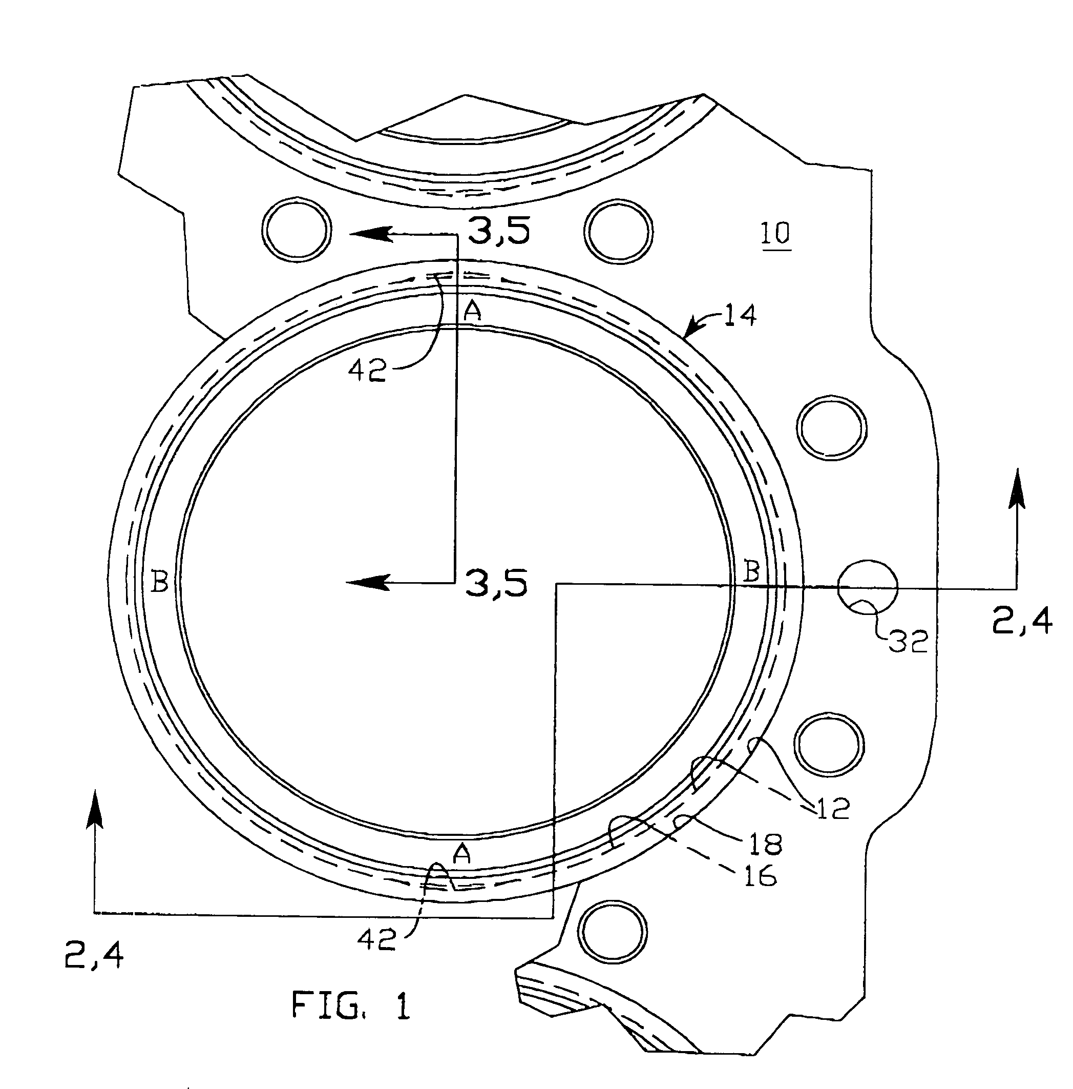
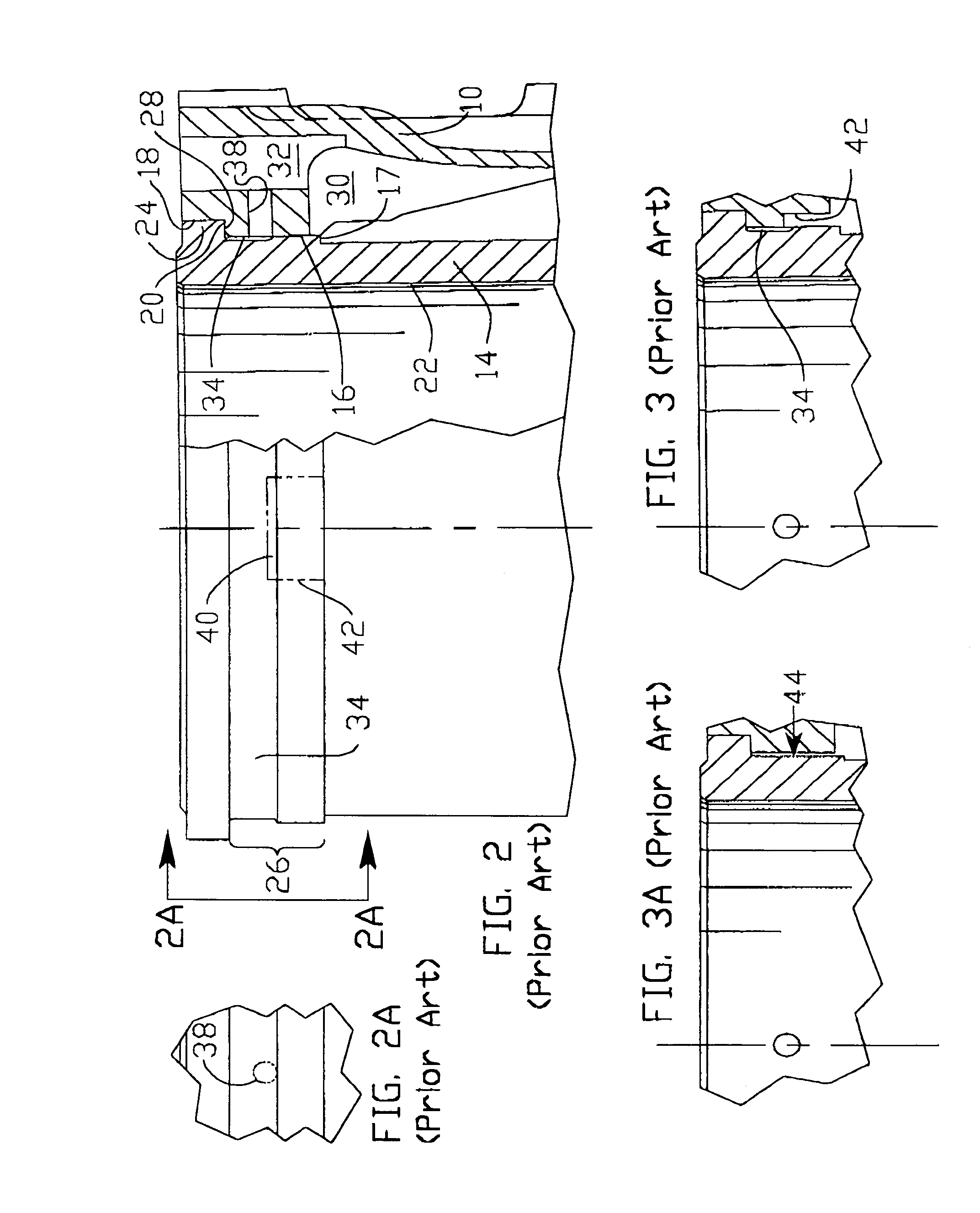
[0023]In the prior-art liner-cylinder-block combination seen in FIGS. 2 and 3, and referring also to FIG. 1, each cylinder bore 12 in the cylinder block 10 receives a cylinder liner 14. Each cylinder bore 12 includes a main inner radial wall 16 of one di...


PUM


Abstract

A coolant-shunt-providing cylinder liner of the flanged type is provided with a shunt circuit within the liner for coolant flow through the liner. The shunt circuit includes an array of three annular cooling channels separated from each other by two annular ribs. The width (axial extent) of each channel is substantially less than half the axial extent of the liner's cylinder block engaging portion that is associated with the upper end of the liner. The width (axial extent) of the array of three channels is substantially greater than half the axial extent of the cylinder block engaging portion. Cutouts in the ribs are provided for distributing incoming coolant to the three cooling channels from a main coolant chamber of a cylinder block in which the liner is receivable.

Description

[0001]This invention relates to diesel cycle internal combustion engines, and specifically to constructions of replaceable shunt-providing cylinder liners of the flange type.BACKGROUND OF THE INVENTION[0002]It is known to designers of cylinder liners that the highest temperatures occurring in a cylinder liner are near the top of the cylinder where the liner abuts the cylinder head, and where the exhaust gasses are driven from the cylinder head through the cylinder head exhaust valves. It is also known to provide annular cooling channels in the liners at these regions of greatest heating. Some examples of the prior art in this field may be briefly described as follows.[0003]In United Kingdom patent 392,091 to Sulzer Freres, annular cooling channels 7–9 are provided in the upper engaging portion of the cylinder liner 1 where it engages and is supported by elements surrounding it including the jacket 5 and annular ring 21. Each of the channels 7–9 is substantially less than half the ax...

Claims


Application Information

Patent Timeline
IPC IPC(8): F02F1/00F02F1/10
CPCF02F1/102F02F1/16
Inventor JONES, JERRY A.GAZIK, THOMAS F.
Owner BUESCHER DEV
Why Eureka
Try Eureka