
Antenna having at least one dipole or an antenna element arrangement similar to a dipole

a technology of dipoles and antenna elements, applied in the direction of antennas, antenna details, antenna feed intermediates, etc., can solve the problems of contact corrosion, significant decrease in the performance of antenna elements, intermodulation problems,

Active Publication Date: 2006-11-07
TELEFON AB LM ERICSSON (PUBL) +1
View PDF35 Cites 28 Cited by
  • Summary
  • Abstract
  • Description
  • Claims
  • Application Information

AI Technical Summary

Benefits of technology

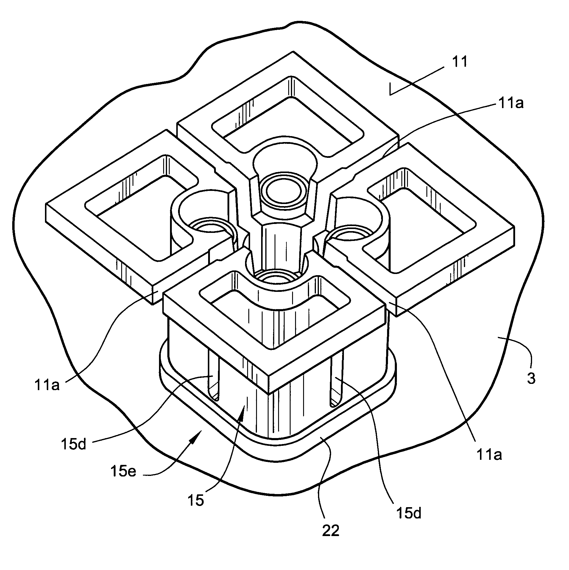
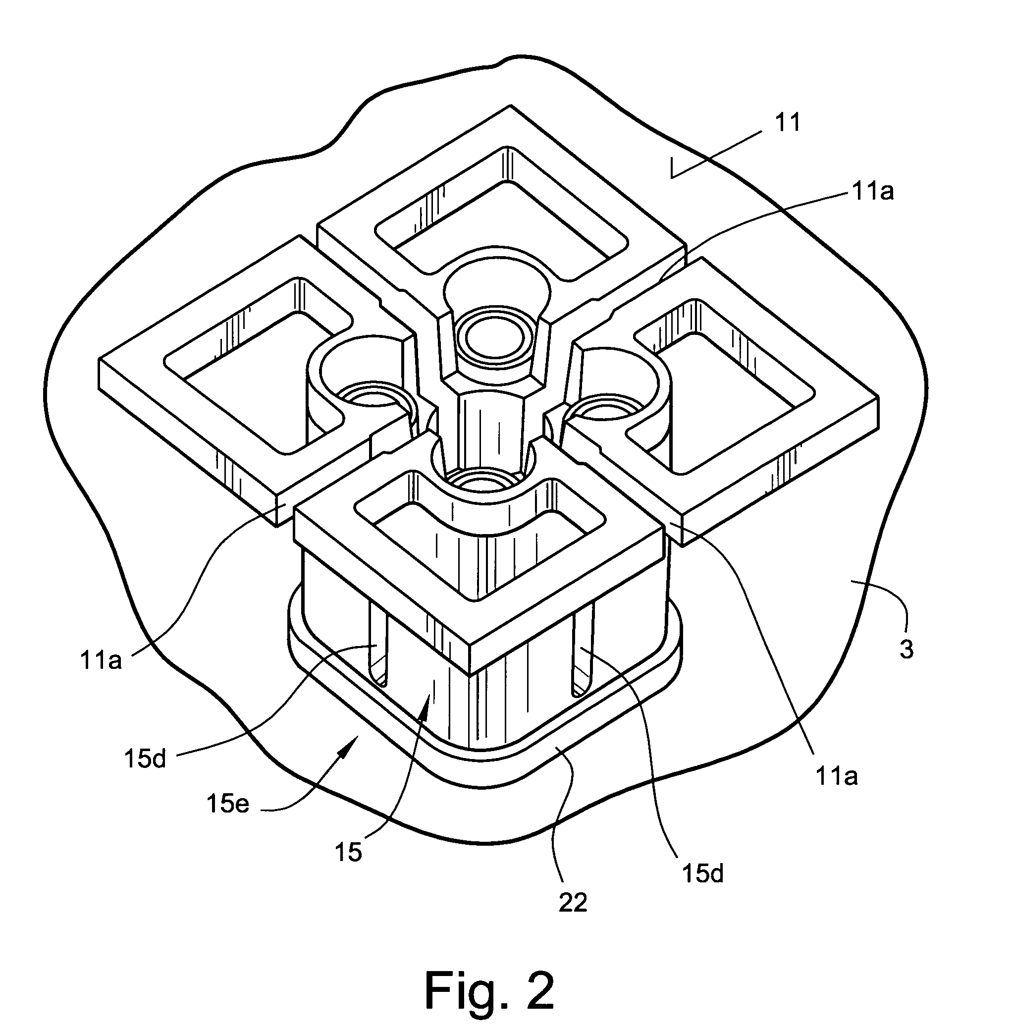
[0005]According to US2004-0201537A1, while avoiding an electrically conductive contact by using capacitive coupling, it is also possible to achieve the further advantage that no voltage potential can occur between the dipole and the reflector. This is because the differently chosen materials for a dipole antenna element or for the mount device for a dipole antenna element and the material for the reflector conventionally otherwise result in an electrochemical voltage which can lead to contact corrosion. Since the exemplary illustrative non-limiting implementation herein avoids this, this also results in a greater range of possible selections for the materials which can be used for the dipole and / or for the reflector.
[0012]In principle, it is also possible for the electrical mount device itself to be formed from non-conductive material, for example plastic. An electrically conductive covering may be drawn over it on the outside. The mount device can then be placed onto the electrically conductive coupling element, which is in the form of a rod, with a sliding face. Preferably, a small amount of play may be provided with the length of the coupling elements which are in the form of rods, also making it possible to ensure that the lower end of the mount device, adjacent to the reflector, cannot make contact with the reflector. Alternatively or in combination, an insulating layer may likewise be formed or provided here, or the end wall of the mount device is not provided with an electrical outer layer at this point.

Problems solved by technology

This is because, when a dipole or antenna elements which are similar to dipoles were mechanically mounted on the reflector plate according to the prior art, they were normally fitted to the reflector plate by means of screws or other connecting mechanisms, thus making it possible for different contact conditions to occur, depending on the installation accuracy, with the consequence that intermodulation problems could occur, which express themselves in different ways.
However, if the contact pressure also decreases, for example because of heat influences, then the contact conditions change, thus resulting in a significant decrease in the performance of an antenna element such as this.
This is because the differently chosen materials for a dipole antenna element or for the mount device for a dipole antenna element and the material for the reflector conventionally otherwise result in an electrochemical voltage which can lead to contact corrosion.

Method used


Image

  • Antenna having at least one dipole or an antenna element arrangement similar to a dipole
  • Antenna having at least one dipole or an antenna element arrangement similar to a dipole
  • Antenna having at least one dipole or an antenna element arrangement similar to a dipole

Examples


Embodiment Construction

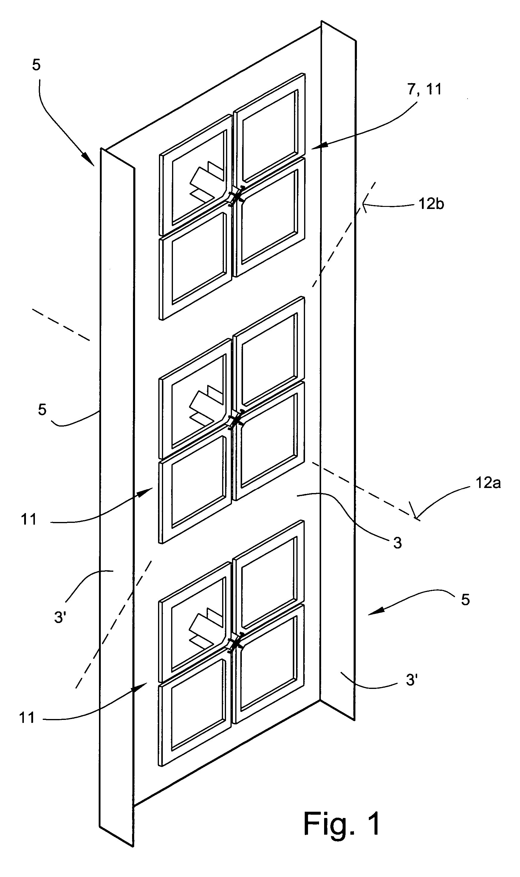
[0033]FIG. 1 shows a schematic illustration of an antenna arrangement 1 with a reflector or reflector plate 3. The reflector 3, for example in the form of a reflector plate, may preferably be provided on both of its opposite longitudinal faces 5, or offset further inwards from these longitudinal faces 5, with a reflector boundary 3′ which, for example, may be aligned at right angles to the plane of the reflector plate 3, or else at an angle which runs obliquely and is not a right angle.

[0034]Two or more dipoles or antenna elements similar to dipoles are normally arranged offset with respect to one another in the vertical direction on a reflector plate 3 such as this. The antenna element or the antenna element arrangements 11 may be formed from single-band antenna elements, dual-band antenna elements, triple-band antenna elements or, in general, from multiband antenna elements or the like. Dual-band antenna elements or even triple-band antenna elements are preferably used for the pre...


PUM


Abstract

An improved antenna includes a coupling element in the form of a rod. The coupling element is electrically conductive and extends transversely with respect to the reflector plane is provided on the front face of the reflector. A mount device has an axial hole in the interior. The axial hole in the mount device can be placed on the coupling element which is in the form of a rod, such that the mount device and the coupling element which is the form of a rod are capacitively coupled, while avoiding any electrically conductive contact.

Description

FIELD[0001]The technology herein relates to an antenna having at least one dipole or an antenna element arrangement which is similar to a dipole.BACKGROUND AND SUMMARY[0002]Dipole antenna elements have become known, for example, from prior publications DE 197 22 742 A and DE 196 27 015 A. The dipole antenna elements may in this case have a normal dipole structure or, for example, may be formed from a cruciform dipole arrangement or a dipole square, etc. A so-called vector cruciform dipole is known, for example, from the prior publication WO 00 / 39894. The structure appears to be comparable to a dipole square. However, in the end, the specific configuration of the dipole antenna element according to this prior publication creates a cruciform dipole structure from the electrical point of view, so that the antenna element formed in this way can transmit and receive in two mutually orthogonally aligned polarizations. All of these prior publications as well as the other dipole structures ...

Claims


Application Information

Patent Timeline
Patent Type & Authority Patents(United States)
IPC IPC(8): H01Q21/26H01Q1/24H01Q9/16H01Q19/10
CPCH01Q1/246H01Q9/16H01Q19/108H01Q21/26
Inventor GOTTL, MAXIMILIAN
Owner TELEFON AB LM ERICSSON (PUBL)
Learn More