Inflatable-collapsible transreflector antenna

a transreflector antenna and collapsible technology, applied in the direction of balloon antennas, antennas, antennas, etc., can solve the problems of reducing the lift capacity, requiring extremely lightweight antenna systems, and antennas that are not designed to be collapsible, so as to achieve the effect of easy collaps

Active Publication Date: 2006-11-07
TOYON RES CORP
View PDF14 Cites 26 Cited by
  • Summary
  • Abstract
  • Description
  • Claims
  • Application Information

AI Technical Summary

Benefits of technology

[0032]This invention provides, among other things, an exemplary embodiment using a transreflector-based antenna that is inflatable and which can be collapsed when not in use. This substantially eases integration of the antenna into an airship which can be the primary antenna platform. Several other types of inflatable antennas (including one spherical reflector, e.g., see U.S. Pat. No. 4,264,053—Hotine) are described in the prior art, but none are designed to be collapsible and have wide scan (e.g., 360-degree) capabilities.
[0033]Another feature of an exemplary embodiment of this invention is a possibly reinforced thin-film, single-wall spherical reflector construction with a thin metallized linear transreflector grating pattern. The metallized strips of the grating preferably have a width that is about half their center-to-center spacing which is, in turn, much less (e.g., <⅛) the shortest RF wavelength to be utilized by the antenna. This provides an extremely lightweight implementation for a transreflector.
[0034]In an exemplary embodiment, the metallization of the grating pattern can be much thinner than the RF current skin depth at a particular frequency to help minimize the transreflector weight.
[0038]An exemplary embodiment of this invention allows the antenna to be readily collapsed to a much smaller volume than when in the fully deployed state, permitting the antenna to share the fully deployed volume when not in use with other structures that may be required for a vehicle which carries such an antenna. Since inflatable structures tend to approach a spherical shape, the single-wall inflatable sphere is the simplest and lightest shape for a stationary 360 degree scanning reflector antenna. The thin film sphere and thin grating metallization allows for an exceedingly lightweight structure that is much lighter than other transreflector shapes and construction methods to provide scanning capability over 360 degrees.

Problems solved by technology

However, since LTA lift capacity is reduced as the vehicle operates at higher altitudes, LTA vehicles require extremely lightweight antenna systems to function in this role at very high altitudes.
However, these antennas are not designed to be collapsible, are fabricated from thick metal rods or wires, or are comprised of multiple singly curved, reflective / transmissive surfaces.
An inflatable spherical reflector is described in U.S. Pat. No. 4,364,053—Hotine but it is not collapsible nor capable of 360 degree scanning.

Method used


Image

  • Inflatable-collapsible transreflector antenna
  • Inflatable-collapsible transreflector antenna
  • Inflatable-collapsible transreflector antenna

Examples


Embodiment Construction

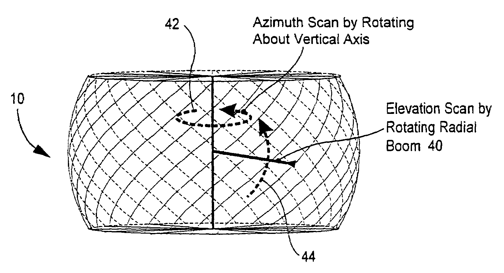
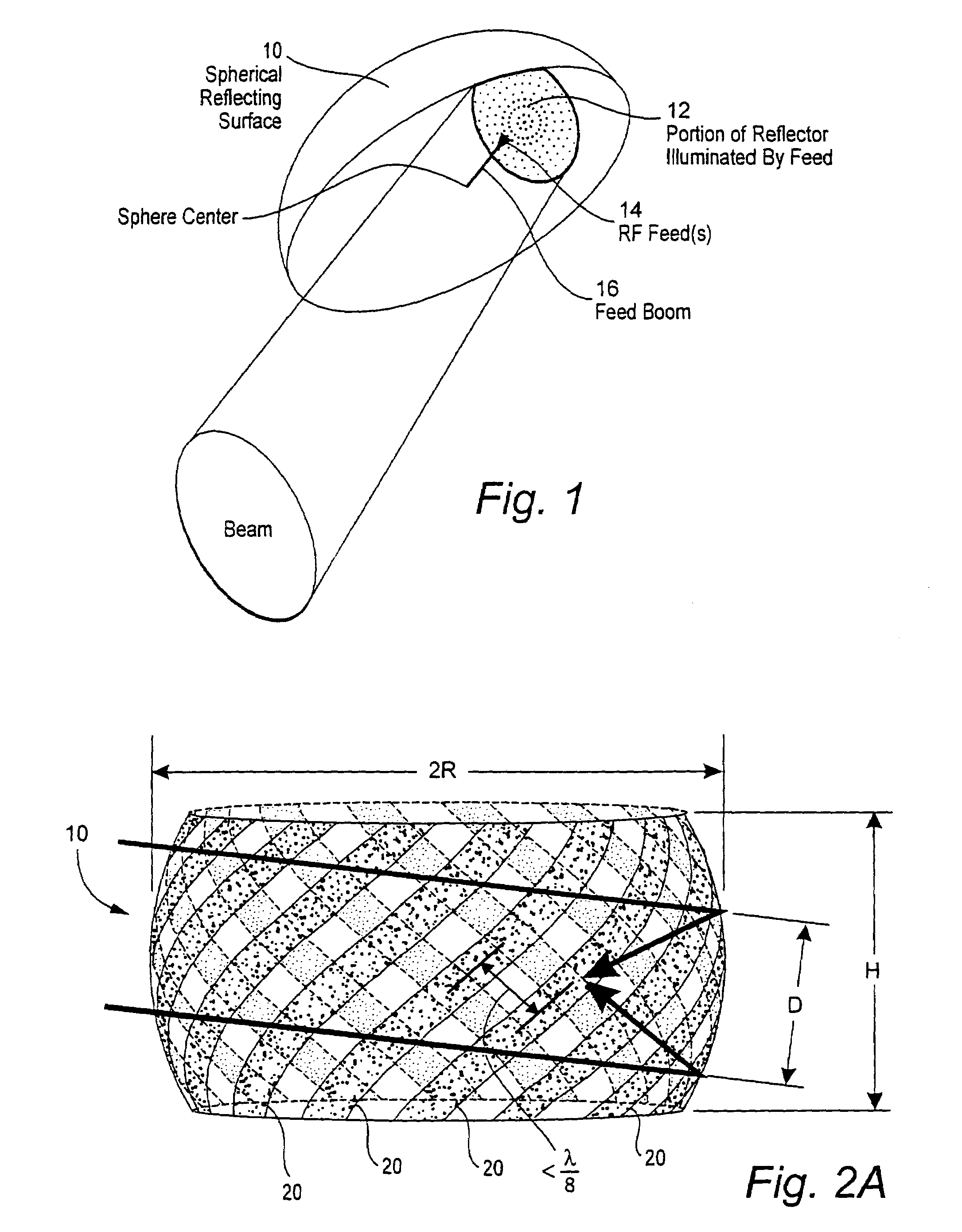
[0053]A presently preferred exemplary embodiment of this invention uses an inflatable-collapsible, spherical reflector antenna (specifically, a transreflector which substantially reflects RF waves from one internal side and which is substantially transparent to RF waves at an opposing side). The spherical transreflector 10 approximates an ideal parabolic shape over a limited portion 12 of the sphere that is illuminated by the feed(s) 14 (i.e., RF ports) as shown in FIG. 1. The reflector is fed at 14 using one or more horns, phased arrays, or other RF feed antennas mounted via a feed boom 16 or the like in the interior of the sphere positioned anywhere on the focal surface located approximately at the sphere half-radius. As will be appreciated by those in the art, the optimum feed location for maximum directivity, as limited by reflector phase errors, depends on the illumination frequency, illumination amplitude and phase, phase pattern, and the size of the reflector.

[0054]The beam i...


PUM


Abstract

A large aperture lightweight antenna uses an inflatable spherical surface deployed within a lighter than air platform. Beam steering is accomplished by moving the RF feedpoint(s) with respect to the reflector. The antenna can use an inflatable collapsible transreflector.

Description

RELATED APPLICATION[0001]This non-provisional application claims the priority benefit under 35 U.S.C. §119(e) of provisional application 60 / 516,280 filed Nov. 3, 2003 (entitled LARGE-APERTURE, LIGHTWEIGHT ANTENNAS FOR LIGHTER-THAN-AIR PLATFORMS) the entire content of which is hereby incorporated hereinto by reference.STATEMENT RE: FEDERALLY SPONSORED RESEARCH DEVELOPMENT[0002]Parts of this invention were described in a February 1996 proprietary proposal to a Federal agency by Toyon Research Corporation.[0003]Parts of this invention were also described in a related February 1998 report by Toyon Research Corporation with[0004]“Distribution limited to U.S. Government agencies only / Test and Evaluation; February 1998. Other requests for this document must be referred to Commander, U.S. Army Missile Command, Attn: AMSMI-RD-WS-DP, Redstone Arsenal, Ala. 35898-35248.”[0005]This report covered studies by Toyon sponsored by Defense Advanced Research Projects Agency (Information Technology Off...

Claims


Application Information

Patent Timeline
Patent Type & Authority Patents(United States)
IPC IPC(8): H01Q15/20H01Q1/28H01Q15/16
CPCH01Q1/082H01Q1/28H01Q15/163H01Q15/20
Inventor MRSTIK, A. VINCENTGILBERT, MICHAEL A.GRACE, MICHAEL P.
Owner TOYON RES CORP
Why Eureka
Try Eureka