System of feature-based surface mapping

a surface mapping and feature-based technology, applied in the field of displacement or offset surfaces, can solve problems such as undersampled or coarse offset surfaces, artifacts that are particularly noticeable, shadowing and reflection are also problematic,

Inactive Publication Date: 2006-11-07
AUTODESK INC
View PDF4 Cites 25 Cited by
  • Summary
  • Abstract
  • Description
  • Claims
  • Application Information

AI Technical Summary

Benefits of technology

[0011]It is an aspect of the present invention to provide a system for generating a high-q...

Problems solved by technology

Bump mapping perturbs surface normals but does not alter the actual surface geometry, causing artifacts that are particularly noticeable from silhouette views.
Shadowing and reflection are also problematic.
This offsetting operation presents numerous problems, including problems in performing the offset operation, and problems with the final offset surface, which is usually a polygonal mesh.
As a result, a vertex-sparse original mesh often results in a displaced mesh that has too few vertices to accurately represent complex features of the height field, such as curves and edges, resulting in an undersampled or coarse offset surface.
Furthermore, offsetting a vertex-dense original mesh requires increased computing resources, and often results in a displaced mesh t...

Method used


Image

  • System of feature-based surface mapping
  • System of feature-based surface mapping
  • System of feature-based surface mapping

Examples


Embodiment Construction

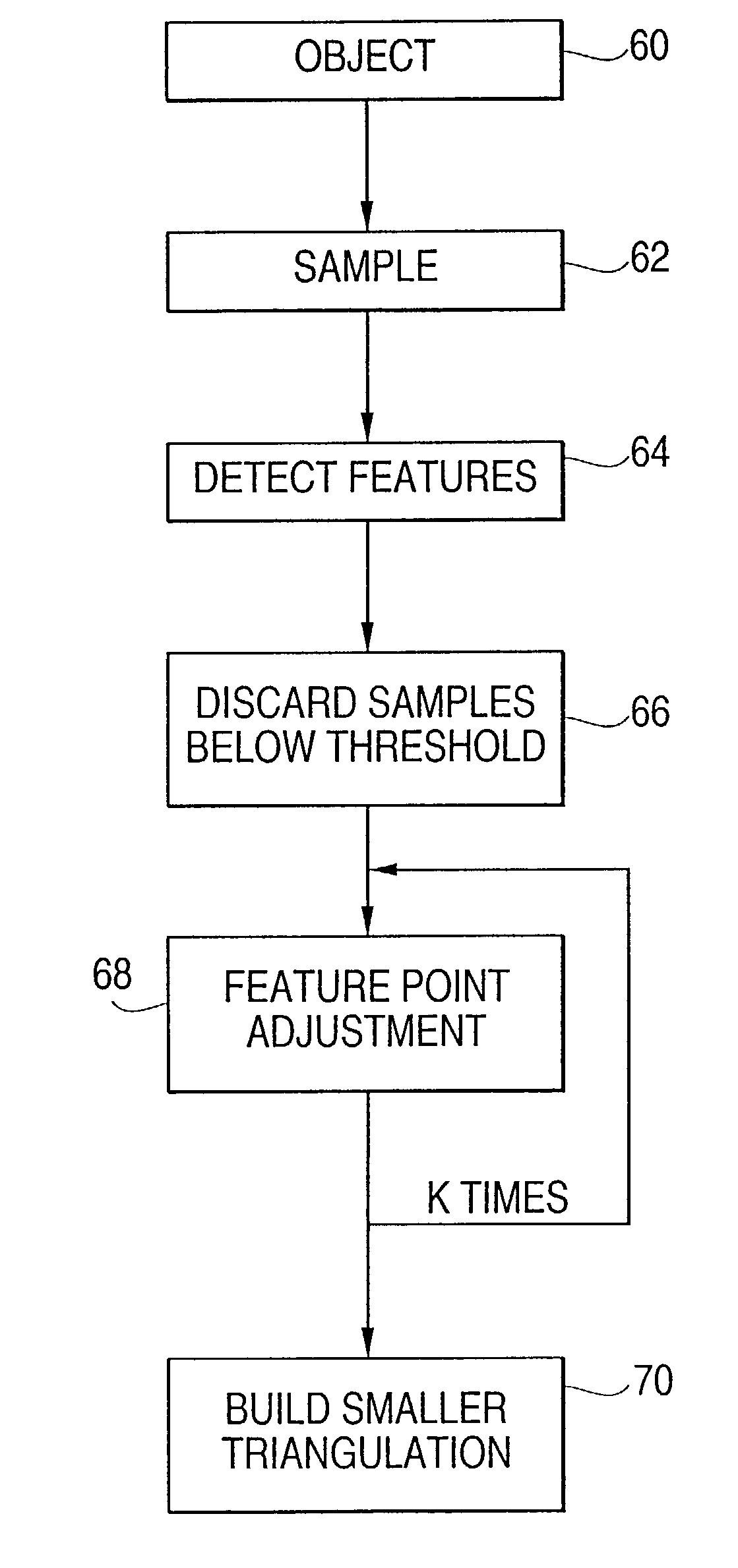
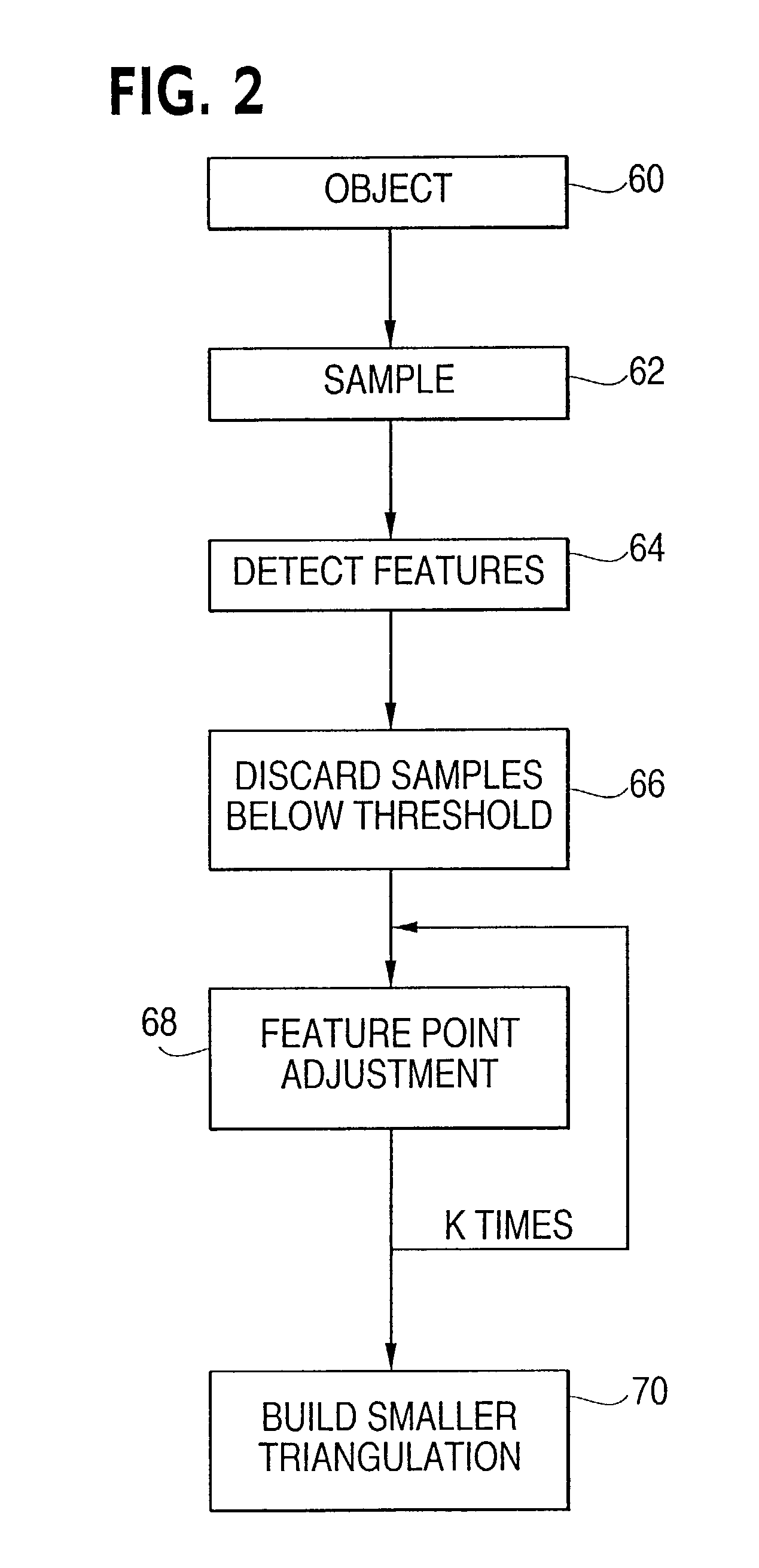
[0052]FIG. 2 shows a flowchart of a method according to an embodiment of the invention. Initially, an object is input 60. The object is sampled 62 in the height field resulting in a height map. Following the sampling 62, the method detects features 64 in the height map. Based on the features, samples below a threshold are discarded 66. The remaining feature points are adjusted 68 and new points are added, possibly repeated k times. Finally the feature points are used to build a smaller triangulation 70.

[0053]FIG. 3 shows an original surface 80 including a sinusoidal wave displacement area 82 colored white, and a non-displaced area 84 colored black. The displacement area 82 is an area that will be offset by a displacement function. The non-displaced area is an area of the original surface 80 that remains unchanged. The present invention offsets a surface, as for example original surface 80, by analyzing a height field to find details of the height field. An original surface is divide...


PUM


Abstract

A method of displacing a tessellated surface, based on features of a displacement map, by analyzing a model to determine the level of detail in the model. Where the level of detail is high the number of polygons, typically triangles, used to represent the high detail area is increased through the use of “sub-triangles”. The positions of the sub-triangles are also strategically located and constrained to better represent the high detail area, particularly any edges in the area. The level of detail can be determined using a displacement map for the surface. The positions of the triangles can be located by determining feature points (or sub-triangle vertices) in the areas of detail where the feature points can be moved toward the areas of high rate of change and additional feature points can be added. The feature points can be connected to form the sub-triangles with an emphasis or constraint on connecting points along an edge or border.

Description

CROSS-REFERENCE TO RELATED APPLICATION[0001]This application is related to and claims priority to U.S. application entitled “Feature-based displacement mapping”, having Ser. No. 60 / 290,669, by Jerome Maillot and Xiaohuan Wang, filed May 5, 2001 and incorporated by reference herein.BACKGROUND OF THE INVENTION[0002]1. Field of the Invention[0003]The present invention is directed to displacing or offsetting surfaces and, more particularly, to a system that provides a higher density of tessellation where detail of the object is the greatest.[0004]2. Description of the Related Art[0005]In the field of computer graphics, there are various approaches to adding visual complexity to a surface. Texture mapping and bump mapping have been used to add visual effects to surfaces. Bump mapping perturbs surface normals but does not alter the actual surface geometry, causing artifacts that are particularly noticeable from silhouette views. Both approaches leave the actual geometry of the surface smo...

Claims


Application Information

Patent Timeline
IPC IPC(8): G06T15/30G06T17/20
CPCG06T17/20
Inventor MAILLOT, JEROMEWANG, XIAOHUAN
Owner AUTODESK INC
Why Eureka
Try Eureka