System and method for programming an automation system, based on pulse timing diagrams

a technology of automation system and pulse timing, applied in the field of system and method of programming an automation system based on pulse timing diagram, to achieve the effect of simple and efficient diagnosis

Inactive Publication Date: 2006-11-07
SIEMENS AG
View PDF10 Cites 1 Cited by
  • Summary
  • Abstract
  • Description
  • Claims
  • Application Information

AI Technical Summary

Benefits of technology

[0012]Simple and efficient diagnosis can be achieved by providing the system for overlaying the generated graphical pulse timing diagrams relating to the current operational data in such a way that, if an error is detected, said error will be visualized in the pulse timing diagrams and the represented current operational data.

Problems solved by technology

As regards the programming of stored program controls (SPCs) of an automation system, this means that error-free automated operation of the system is described with the aid of the pulse timing diagrams with no consideration being given to operating modes or the handling of errors.

Method used


Image

  • System and method for programming an automation system, based on pulse timing diagrams
  • System and method for programming an automation system, based on pulse timing diagrams
  • System and method for programming an automation system, based on pulse timing diagrams

Examples


Embodiment Construction

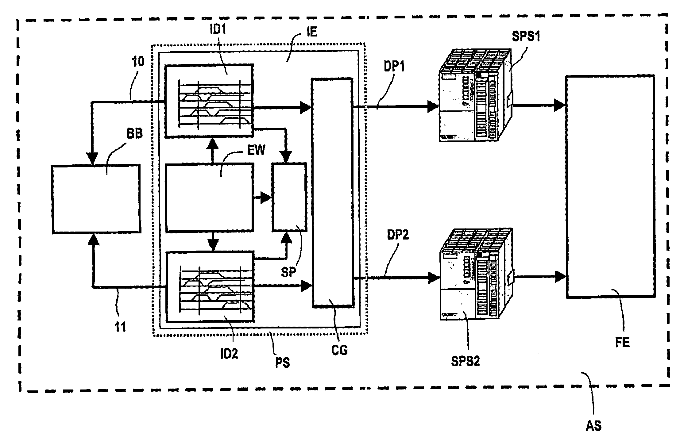
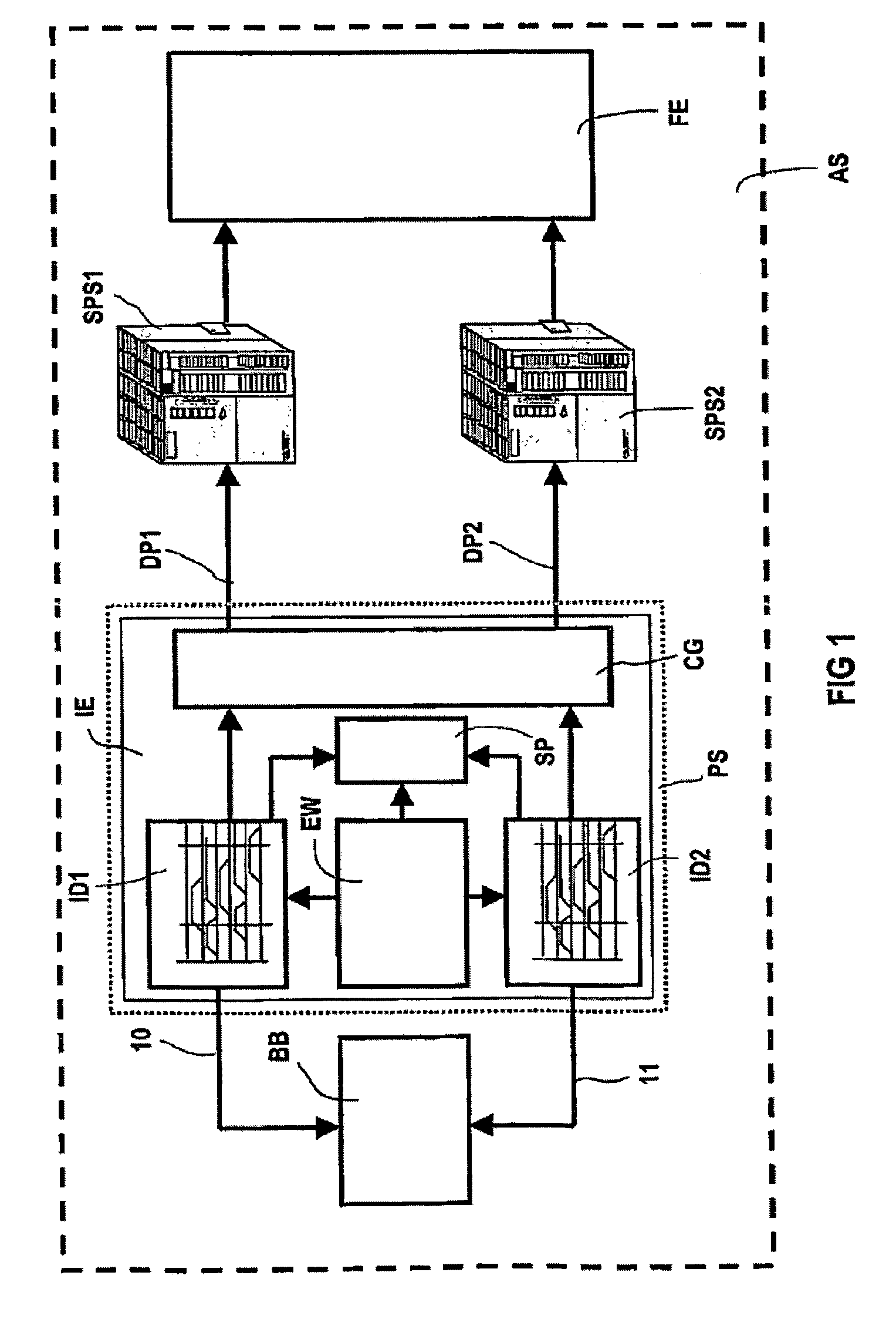
[0022]FIG. 1 is a block diagram of an exemplary embodiment of an automation system AS. Said automation system AS consists of an operating and observation system BB, of stored program controls SPS1, SPS2, and of a production facility FE. The stored program controls SPS1, SPS2 are controlled via data programs DP1, DP2 produced by means of a programming system PS. The programming system PS includes a code generator CG which generates a code which can be processed by the stored program controls. The data programs DP1, DP2 are based on pulse timing diagrams ID1, ID2 and on expansions EW which are generated by means of an intelligent editor TE. The intelligent editor IE further comprises a memory SP for storing the data of the pulse timing diagrams ID1, ID2 and of the expansions EW.

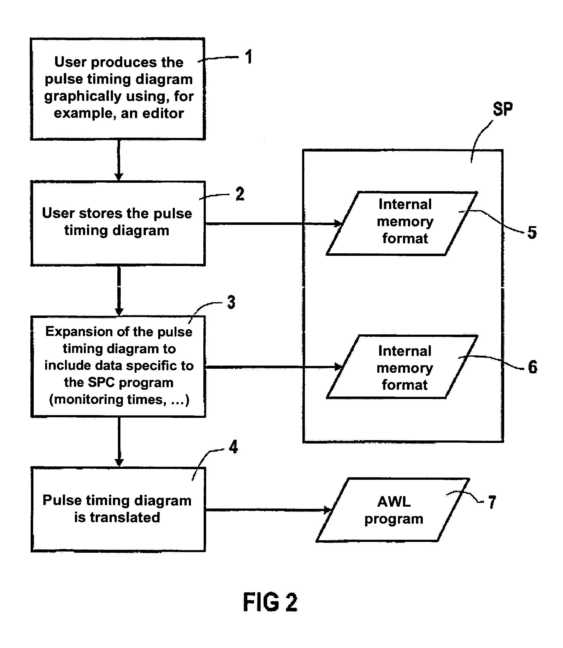
[0023]The basic flow of programming the automation system AS shown in FIG. 1 is described in more detail below. The intelligent editor IE is the central component for producing the data programs DP1, DP2 of the...


PUM


Abstract

The invention relates to a system and method for programming an automation system. To avoid conversion errors and to guarantee data during the programming of an automated system, a graphic description by means of pulse timing diagrams is used to generate a program of the automation system, in particular the program of a memory programmable control. Modifications of the pulse timing diagrams thus lead directly to modifications of the program of the memory programmable control, without the need for a renewed conversion that potentially contains errors.

Description

CROSS REFERENCE TO RELATED APPLICATIONS[0001]This application is the US National Stage of International Application No. PCT / DE02 / 03407, filed Sep. 12, 2002 and claims the benefit thereof. The International Application claims the benefits of German application No. 10147166.1 DE filed Sep. 25, 2001, both of the applications are incorporated by reference herein in their entirety.FIELD OF INVENTION[0002]The invention relates to a system and method for programming an automation system based on pulse timing diagrams.BACKGROUND OF INVENTION[0003]A system and method of this type is employed in the area of automation technology, in particular in production and process automation. This frequently entails the production by the “design department” of pulse timing diagrams, also referred to as pneumatic flowcharts or as path-time diagrams, for describing machine movements. The pulse timing diagrams thus identify a desired course of machine movements. As regards the programming of stored program ...

Claims


Application Information

Patent Timeline
Patent Type & Authority Patents(United States)
IPC IPC(8): G06F19/00G06F9/44G05B19/05
CPCG05B19/056G05B2219/13147G05B2219/13153
Inventor EICHHORN, ANNETTEHOFFMANN, WERNERKIELBURGER, HELMUT
Owner SIEMENS AG
Why Eureka
Try Eureka