Method for diagnosing a torque impulse generator

a technology of torque impulse generator and torque reservoir, which is applied in the direction of portable power-driven tools, manufacturing tools, instruments, etc., can solve the problems of reducing the oil level in the oil reservoir, and affecting the operation of torque impulse generator mechanical parts

Active Publication Date: 2018-05-29
ATLAS COPCO INDAL TECHN AB
View PDF24 Cites 0 Cited by
  • Summary
  • Abstract
  • Description
  • Claims
  • Application Information

AI Technical Summary

Benefits of technology

[0011]The level of oil in the oil reservoir will influence the ability of the torque impulse generator to generate torque. If the level of oil decreases, less rotational energy of the input portion will be converted to torque impulses at the torque output portion. This will thus increase the relative rotation frequency between the rotational input portion and the torque output portion, and thus increase the frequency of torque impulses. By detecting an acoustic signal from the torque impulse generator, extracting the frequency of torque impulses from the acoustic signal and diagnosing the torque impulse generator based on the frequency of torque impulses, the level of oil in the oil reservoir of the torque impulse generator may be indicated. The method allows for simple and efficient diagnosis of torque impulse generators, which may be used at the point of operation of the torque impulse generators, e.g. at an assembly station.
[0021]The torque output may be generated at predetermined operational conditions of the torque impulse generator. Thus the influence of operational conditions on the torque impulse frequency may be minimised.
[0027]One or more of the steps of the method may be performed by a handheld electronic device. The handheld electronic device may e.g. be a phone such as a smartphone. Thus the method is easily accessible by operators of power tools and other personnel.

Problems solved by technology

Due to leakage, the level of oil in the oil reservoir tends to decrease over time.
If the operator of the tool is unable to recognize this there is a risk of faulty tightening and destruction of mechanical parts of the torque impulse generator.

Method used


Image

  • Method for diagnosing a torque impulse generator
  • Method for diagnosing a torque impulse generator
  • Method for diagnosing a torque impulse generator

Examples


Embodiment Construction

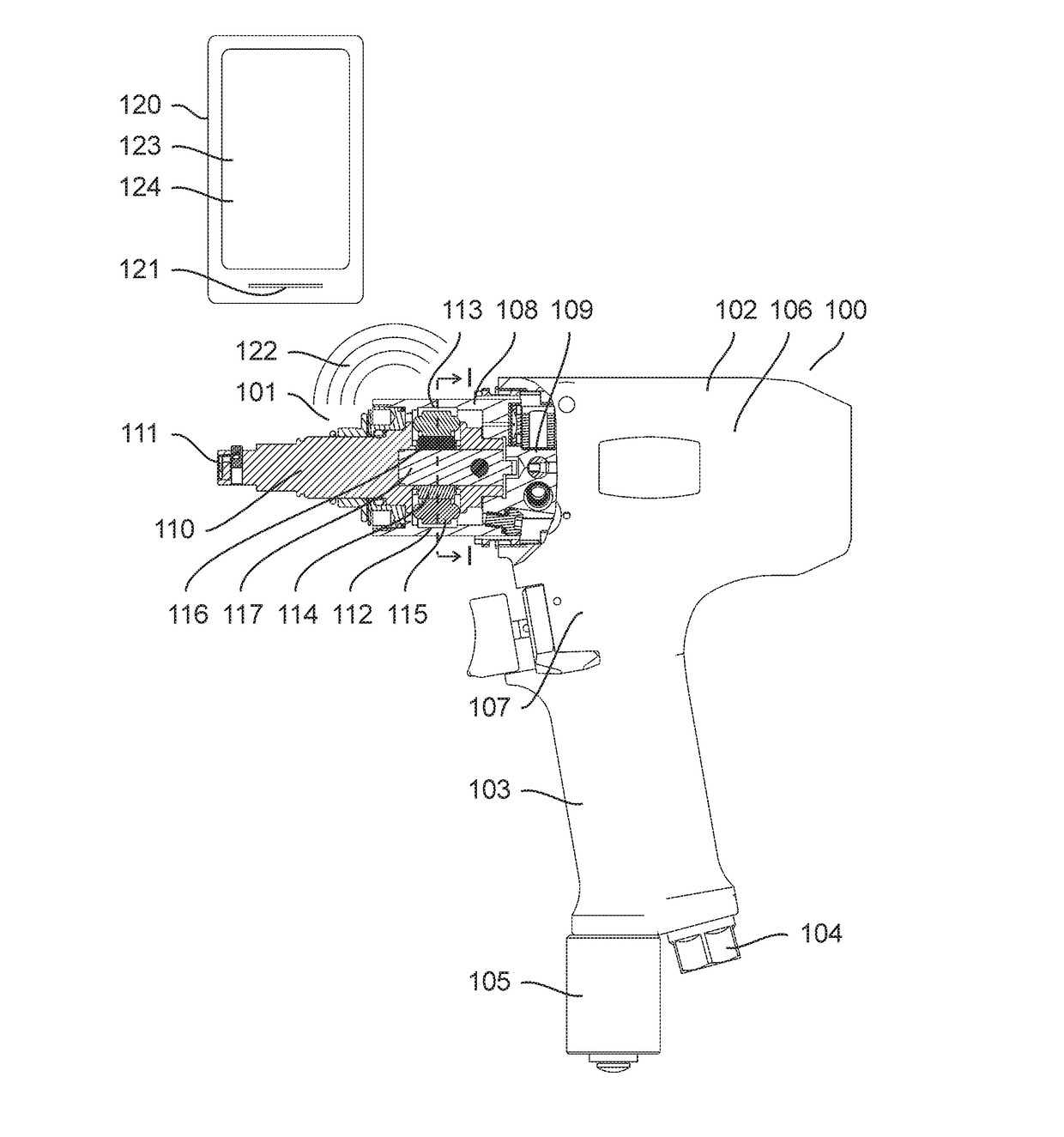
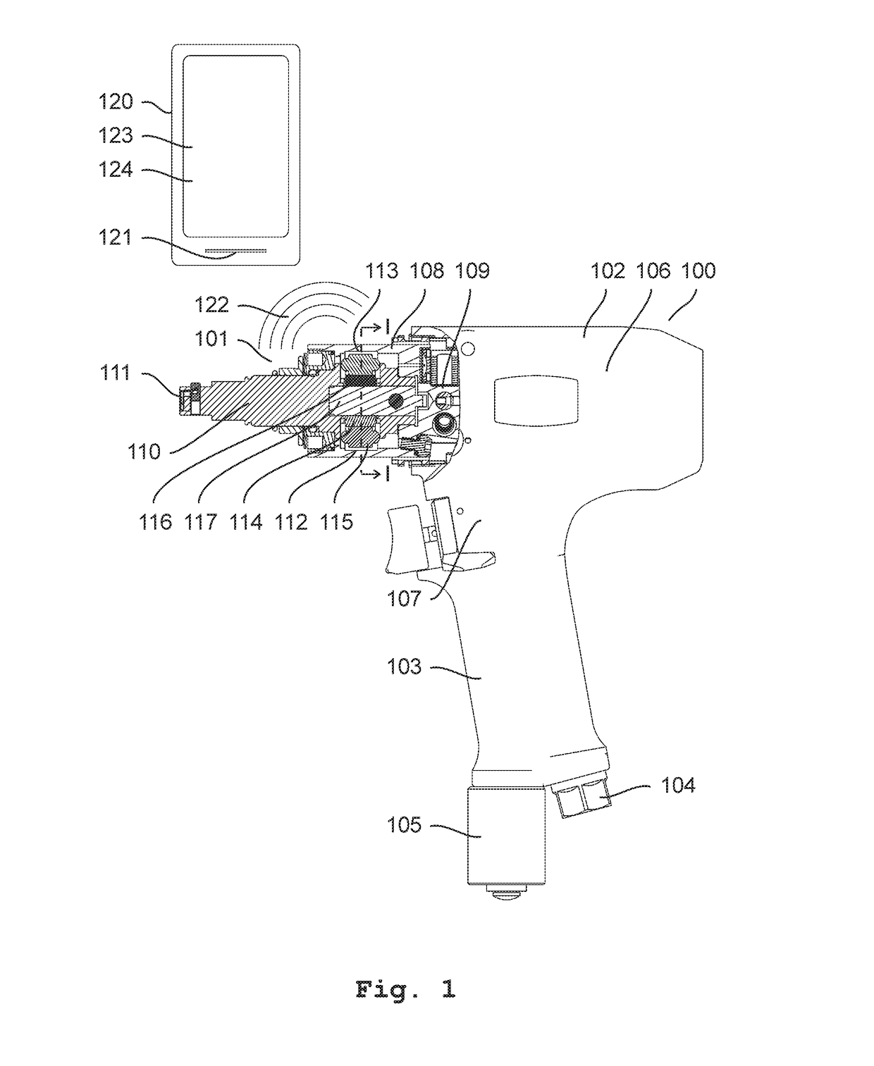
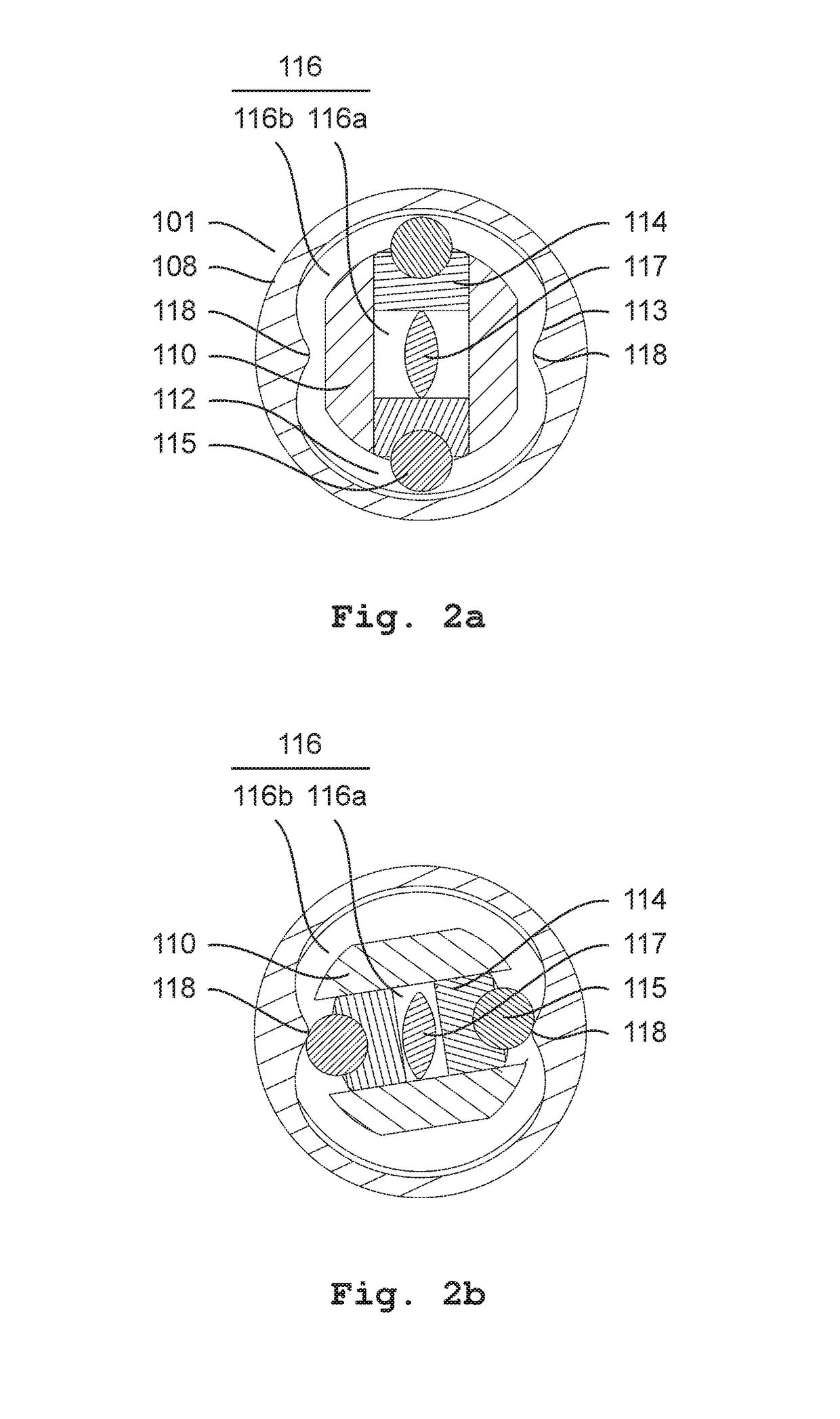
[0036]FIG. 1 shows a power tool 100 comprising a torque impulse generator 101. The power tool further comprises a housing 102 having a handle 103, an air supply 104 and an air exhaust 105. The air supply is connected to an air motor 106 (not shown) via a throttle valve 107. The torque impulse generator comprises a rotational input portion 108 comprising a shaft 109 connected to the air motor, and a torque output portion 110 having an output shaft for supporting a tool bit or a quick tool change chuck. The torque impulse generator further comprises a torque generating arrangement 112 converting rotation of the input portion to torque impulses at the torque output portion. The torque generating arrangement 112 comprises a cam 113 formed on the inside of the rotational input portion 108, and a pair of cam followers in the form of a pair of pistons 114 and rollers 115. The space formed radially inside the pistons, and the space formed radially inside the rotational input portion 108 and...


PUM


Abstract

A method for diagnosing a torque impulse generator which includes a rotational input portion, a torque output portion, an oil reservoir and a torque generating arrangement converting rotation of the input portion to torque impulses at the torque output portion, the method includes: detecting an acoustic signal from the torque impulse generator while generating torque impulses, extracting the frequency of torque impulses from the acoustic signal, and diagnosing the torque impulse generator based on the frequency of torque impulses, to indicate the level of oil in the oil reservoir.

Description

[0001]The invention relates to a method for diagnosing a torque impulse generator.BACKGROUND[0002]Pulse tools, i.e. power tools comprising a torque impulse generator, are e.g. used to tighten joints during an assembly operation. Such torque impulse generators comprise a rotational input portion, a torque output portion, an oil reservoir and a torque generating arrangement converting rotation of the input portion to torque impulses at the torque output portion.[0003]In U.S. Pat. No. 5,092,410 A, EP 0885693 B1 and WO 2011141205 A1 various types of torque impulse generators are shown.[0004]The performance of a torque impulse generator is dependent on the level of oil in the oil reservoir. Due to leakage, the level of oil in the oil reservoir tends to decrease over time. When the oil level decreases, the ability of the torque impulse generator to generate torque will decrease. If the operator of the tool is unable to recognize this there is a risk of faulty tightening and destruction of...

Claims


Application Information

Patent Timeline
Patent Type & Authority Patents(United States)
IPC IPC(8): B25B21/02B25B23/14B25F5/00B25B23/145G01F23/296
CPCG01F23/296B25B21/02B25F5/00B25B23/1453B25B23/14
Inventor NELSON, ANDERS URBANWIKLUND, NICLAS MIKAEL
Owner ATLAS COPCO INDAL TECHN AB
Why Eureka
Try Eureka