Tube bender

a tube bender and tube technology, applied in the field of tube benders, can solve the problems of not being so well qualified to produce perfect tubes, difficult to control the size of tubes after bending, and disqualified products

Active Publication Date: 2006-11-14
YING HAN TECH CO LTD
View PDF7 Cites 26 Cited by
  • Summary
  • Abstract
  • Description
  • Claims
  • Application Information

AI Technical Summary

Benefits of technology

[0008]When the tube pushing device pushes a tube being bent to the bending device, the tube-bending device carries out sidewise bending to the tube with conjunction with the guide mold to prevent the tube from disfiguring of the bent section.
[0009]2. Comparing with the conventional pull-style or push-style tube bender, the tube bender in the present invention uses the tube pushing device for pushing a tube being bent to be clamped by the tube bending device fixed on the other end of a worktable, and after that it does not give push force, and the bending mold of the press-style bending device adds force to the tube sidewise, with cooperation of the guide mold, pressing the tube directly and surely in the gap between the guide mold and the bending mold during rotation of the bending mold so as to shape the tube being bent into a bent one so as to get a bent tube having a comparatively correct size, improving the quality of a finished bent tube and the disadvantage that the conventional pull-style or push-style tube bender has.

Problems solved by technology

However, the processes of bending by pulling may easily cause clamping scars and disfiguring to result in disqualified products, because the tube being bent is clamped by the roller unit of the bending device and then clamped by the bending unit of the bending device for carrying out bending action.
Though the case of the Italian patent can improve the drawback of easy disfigure of a tube after bent, the tube is not actually contact completely to the roller mold of the guide mold in performing bending action, so it is not easy to control the size of the tube after bent, still not so well qualified for producing perfect bent tubes.

Method used


Image

  • Tube bender
  • Tube bender
  • Tube bender

Examples


Embodiment Construction

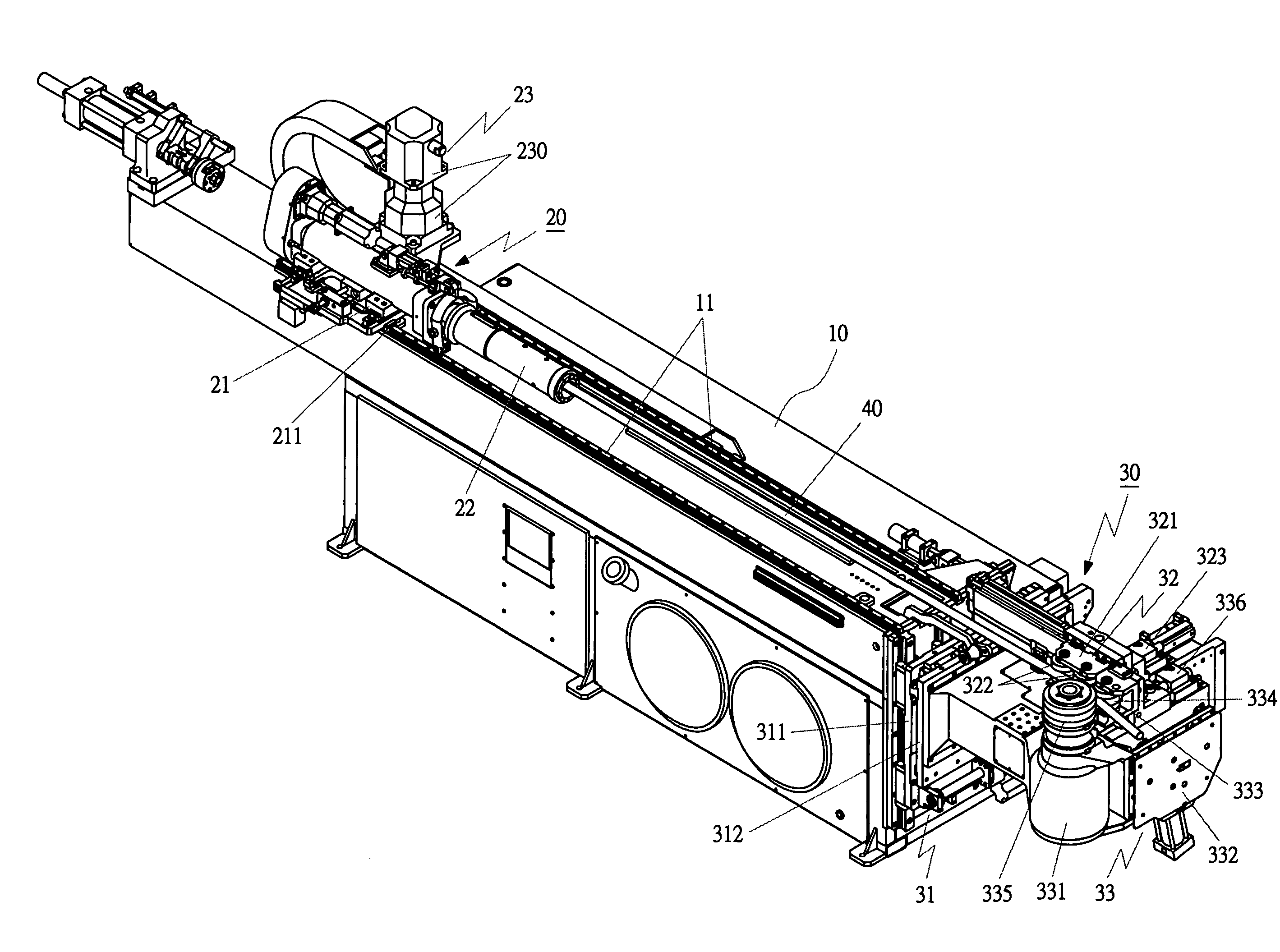
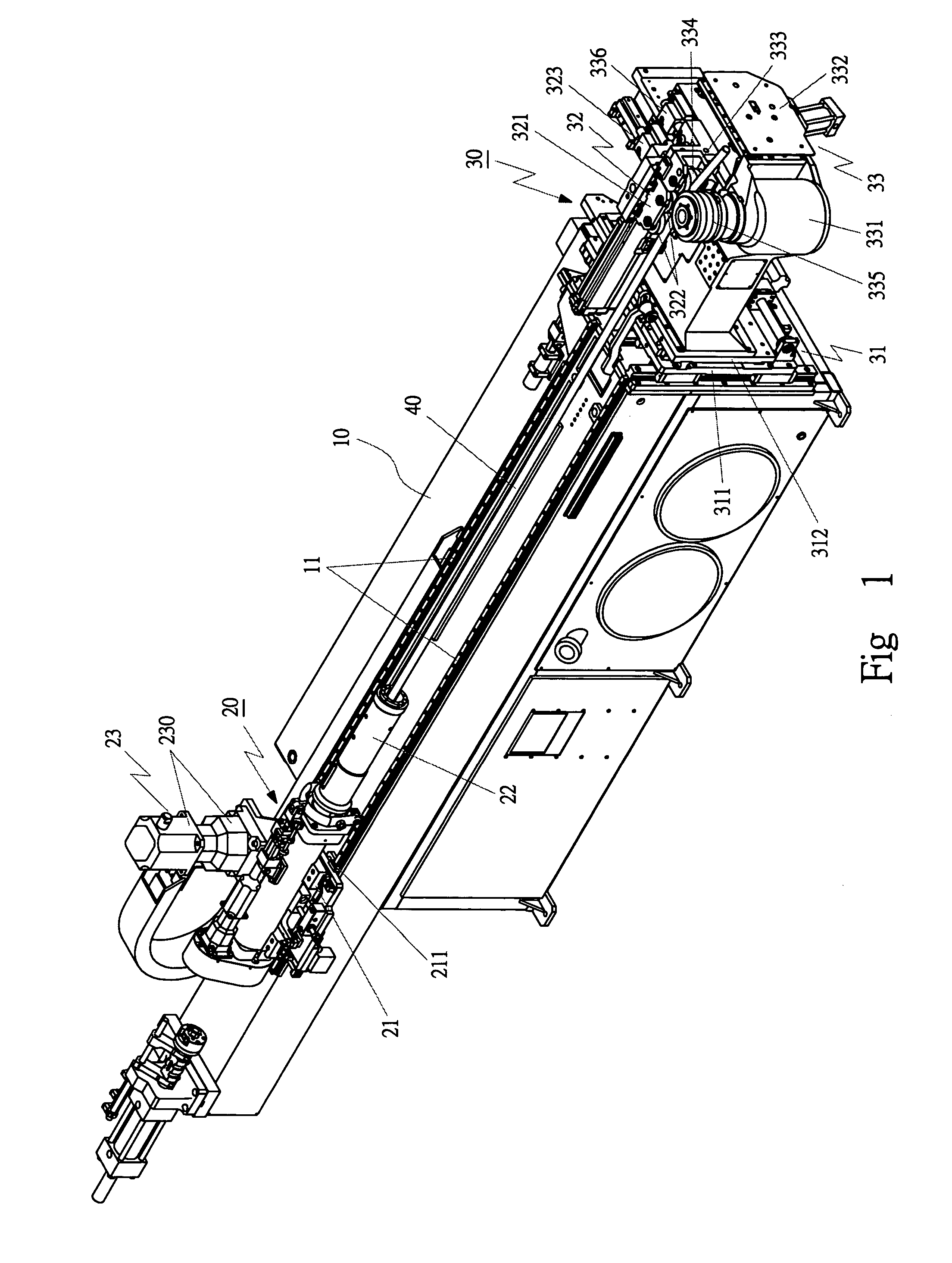
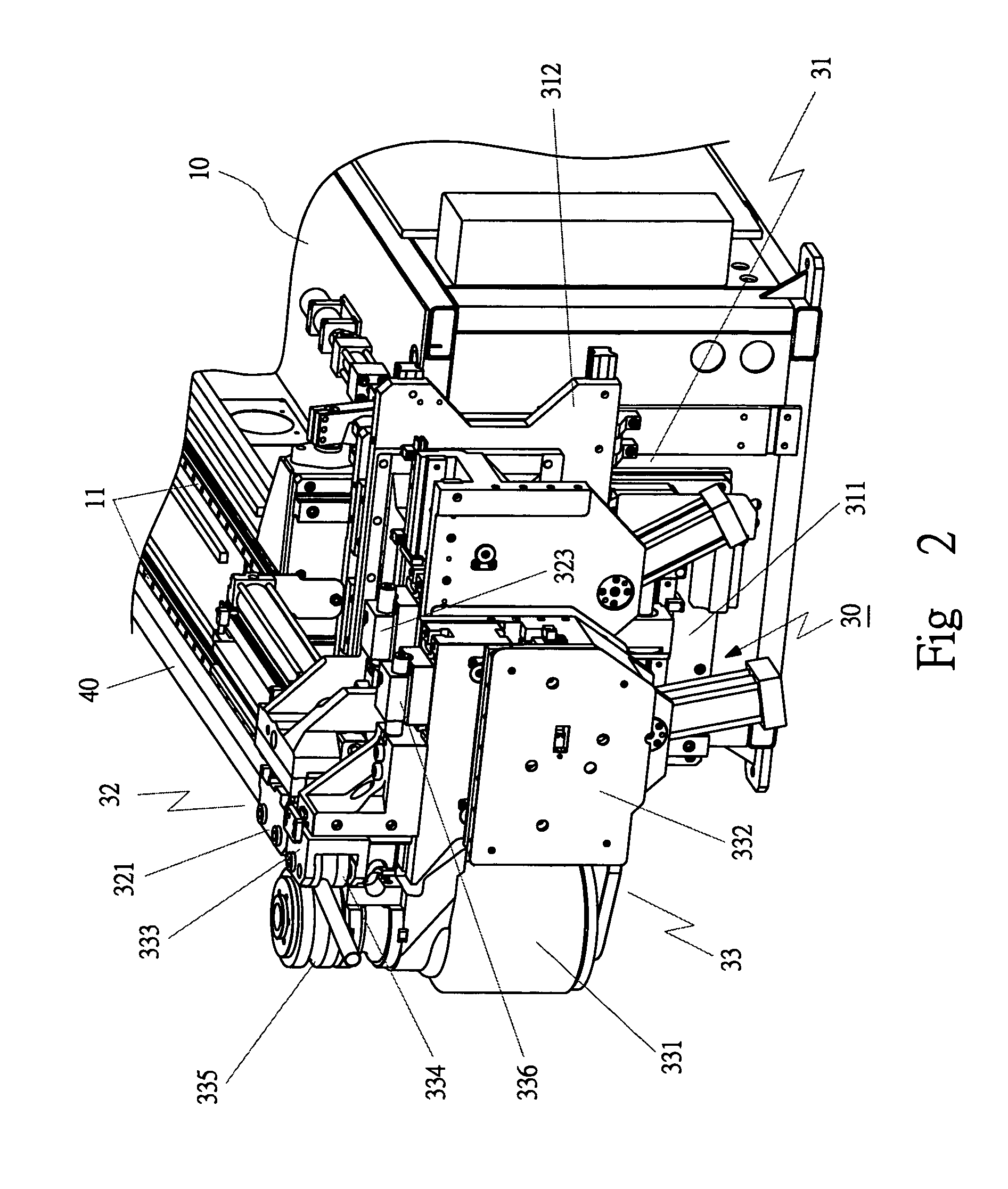
[0023]A first embodiment of a tube bender in the present invention, as shown in FIGS. 1, 2 and 3, includes a worktable 10, a tube-pushing device 20, and a tube-bending device 30 as main components combined together.

[0024]The worktable 10 has a number-style controlling device (not shown) belonging to a CNC number-style controlling system, and a rail 111 fixed on the worktable 10.

[0025]The tube pushing device 20 is positioned on the worktable 10, consisting of a moving base 21, a clamper 22, and a driver 23. The moving base 21 has a rail groove 211 symmetrically provided at two sides and connected with the rail 11 in a dovetail condition to let the moving base 21 to move smoothly on the rail 11. The clamper 22 is located at one side of the moving base 21, controlled by the controlling device for clamping and loosening a tube 40 being bent. The pushing driver 23 is connected with the moving base 21, consisting of a motor and a gear case 230, and using oil pressure or a threaded rod for...


PUM

PropertyMeasurementUnit
speedaaaaaaaaaa
shapeaaaaaaaaaa
forceaaaaaaaaaa

Abstract

A tube bender includes a worktable, a rail on the worktable, a tube-pushing device and a tube-bending device. The tube-pushing device is positioned on the worktable, having a moving base and a clamper at one side of the moving device. The clamper clamps a tube being bent, and a push driver moves the moving base together with the tube work to a preset location. The tube-bending device consists of a base unit, a guide unit and a driving unit, and when the tube work is moved to the tube-bending device, it is bent by the tube-bending device, with a guide roller and a main roller sandwiching the tube for preventing the bent section of the finished tube from disfiguring.

Description

FIELD OF THE INVENTION[0001]This inventin relates to a tube bender, particularly to one provided with a tube pushing device for moving a tube to be bent to a tube bending device, which then performs bending the tube sidewise, and with guide rollers performing bending action so as not to let the bent section disfigure.BACKGROUND OF THE INVENTION[0002]Conventional tube benders are commonly used for bending tubes, classified into a pull-style and a push-style ones. The pull-style tube bender is provided with a worktable, a control device fixed on the worktable, a tube pushing device positioned on the worktable to move longitudinally, and a pull-style bending device positioned on an end of the worktable. In bending a tube, a tube being bent has its one end clamped tightly in a clamper of the tube-pushing device, and its other end facing toward the tube-bending device. Then the tube being bent is moved in a preset speed by the control device to the tube-bending device. Subsequently, the ...

Claims


Application Information

Patent Timeline
Patent Type & Authority Patents(United States)
IPC IPC(8): B21D7/025
CPCB21D7/021B21D7/024
Inventor HU, PING-KUN
Owner YING HAN TECH CO LTD
Why Eureka
Try Eureka