Vacuum gate valve

a vacuum gate valve and valve plate technology, applied in the direction of valve member-seat contacts, valve operating means/release devices, mechanical devices, etc., can solve the problems of poor tightness, damage to the sealing surface or the sealing ring, and the valve plate is not aligned properly, so as to simplify the design of parts and facilitate the operation and maintenance. , the effect of high reliability

Active Publication Date: 2006-11-14
VAT HLDG AG
View PDF21 Cites 48 Cited by
  • Summary
  • Abstract
  • Description
  • Claims
  • Application Information

AI Technical Summary

Benefits of technology

[0017]Exemplary embodiments provide a vacuum gate valve of high reliability, simplified handling and maintenance, and a simple parts design.
[0018]Exemplary embodiments provide a vacuum gate valve having a joint between valve rod and valve plate such that the alignment of the valve plate around the valve rod axis can adapt to the valve seat, at least when pressure is applied for a first time, by providing a turning capability.
[0019]Exemplary embodiments reduce the need for tedious precise pre-alignment of the valve plate. Contact between the valve housing and the valve plate can be avoided by the use of means confining the turning capability while the valve plate is moved over the opening.

Problems solved by technology

A particular problem in the related art is the alignment of valve plate 5 relative to valve housing 1.
In the first step, moving the valve plate 5 over the opening 3, contact of the sealing face 7 with wall 2 or valve seat 4 can lead to injury to a sealing surface or to the sealing ring.
In related art systems the planes of sealing face 7 and valve seat 4 should be parallel while the pressure is applied, since otherwise the sealing surface along the valve seat would be stressed non-uniformly, which could give rise to poor tightness and to a degradation of the sealing material.
With the vacuum gate valves known from the related art, the demounting and re-mounting of the valve plate is found to be difficult, since an intervention from several sides of the valve plate is required to detach the valve plate from the valve rod, e.g. in order to unfasten any mounting screw and take off the valve plate from the valve rod.
A safe demounting is not readily achieved without injury to the valve plate 5 or valve housing 1, and particularly the valve seat 4, because of poor ergonomic possibilities for handling the valve plate.

Method used


Image

  • Vacuum gate valve
  • Vacuum gate valve
  • Vacuum gate valve

Examples


Embodiment Construction

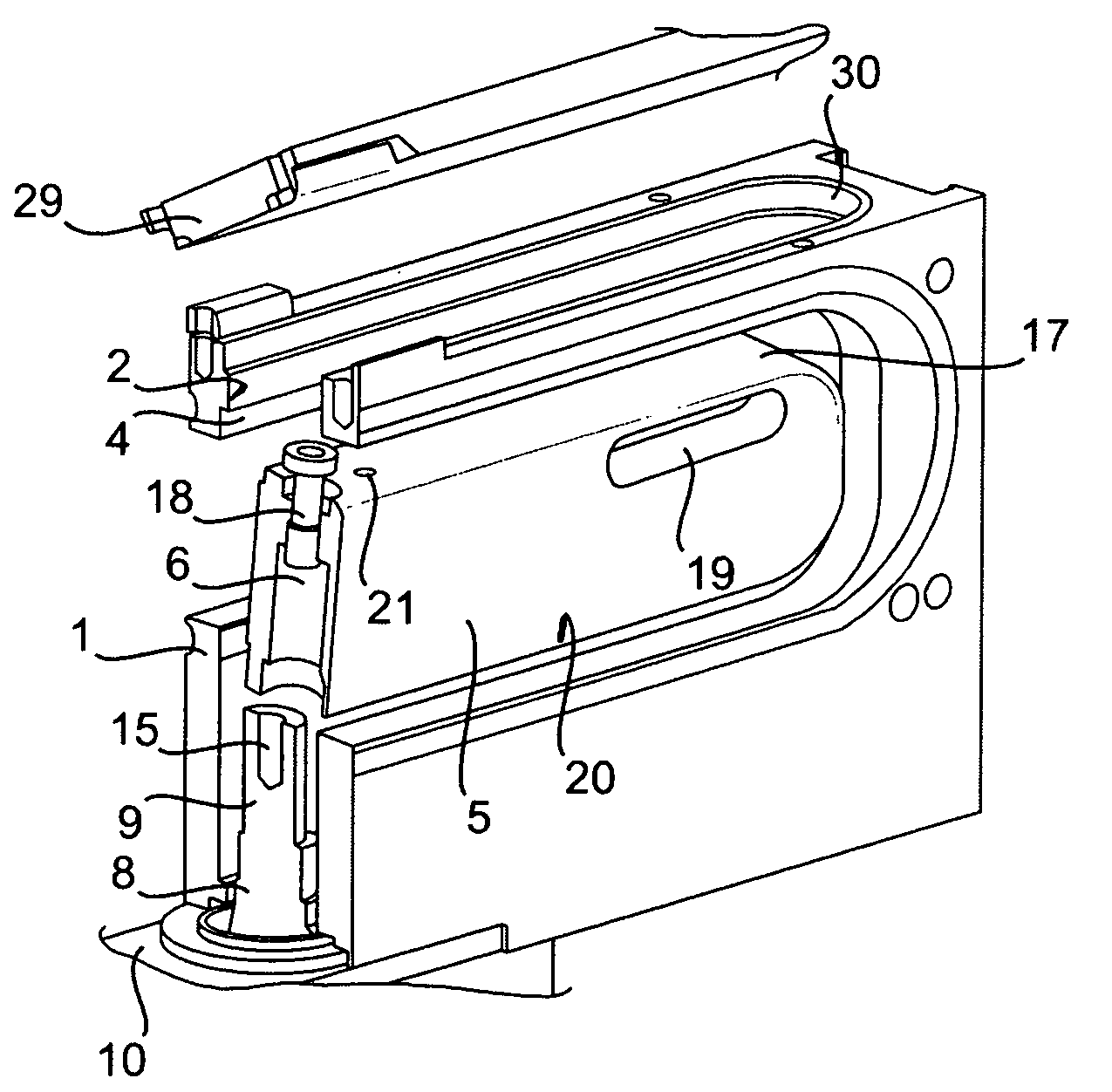
[0033]Vacuum gate valves in accordance with at least one embodiment have a valve housing with a wall having an opening and a valve seat surrounding the opening. The opening can have an open section (e.g. rectangular, elliptical, and the like) with variously shaped corners (e.g. rounded corners, straight corners and the like).

[0034]In at least one exemplary embodiment, a valve seat can have a wall segment functioning as a sealing surface onto which another surface acting as a sealing surface can be applied. A housing may also be formed by the wall segment. The opening can be closed off by a valve plate. The valve plate can have various shapes (e.g. a rectangular section and the like) such that the sealing surface is dimensioned so that the opening can be closed off with an overlap by the valve plate.

[0035]In at least one exemplary embodiment, a sealing ring is fixed to the rim of the sealing face for application to the valve seat. The valve plate is mounted detachably on a valve rod....


PUM


Abstract

The invention provides a vacuum gate valve for closing off an opening. The vacuum gate valve can have a valve plate that can be turned so that the alignment of the valve plate will adapt to a valve seat when the valve plate is pressed against the valve seat.

Description

CROSS-REFERENCE TO RELATED APPLICATIONS[0001]This nonprovisional application claims priority under 35 U.S.C. § 119 of South Korean application No. 10-2004-0017074, filed 12 Mar. 2004, which is herein incorporated by reference in its entirety.FIELD OF THE INVENTION[0002]The invention relates in general to vacuum gate valves.BACKGROUND OF THE INVENTION[0003]Vacuum gate valves are used to close off an opening in a container or pipeline. Vacuum gate valves primarily of the L-type are utilized in IC and semiconductor manufacturing to exclude, to a large extent in a protected atmosphere, the presence of contaminating particles. For instance, in a production unit for semiconductor wafers or liquid-crystal substrates, the highly sensitive semiconductor or liquid-crystal elements pass through a number of production chambers each of which can be connected to the next via a connecting passage. These passages are opened via vacuum gate valves so that the elements can be transferred from one pro...

Claims


Application Information

Patent Timeline
Patent Type & Authority Patents(United States)
IPC IPC(8): F16K3/16F16K3/00F16K3/18F16K25/00
CPCF16K3/18F16K3/314F16K51/02
Inventor SEITZ, DANIEL
Owner VAT HLDG AG
Why Eureka
Try Eureka