
Integral slip layer for insulating tape

a technology of insulating tape and slip layer, which is applied in the direction of insulating conductors, cables, conductors, etc., can solve the problems of low resistance of the layer, electric discharge, and insufficient turn insulation b>15/b> to withstand the severe voltage gradient,

Active Publication Date: 2006-11-14
SIEMENS ENERGY INC
View PDF11 Cites 10 Cited by
  • Summary
  • Abstract
  • Description
  • Claims
  • Application Information

AI Technical Summary

Benefits of technology

"The present invention provides a non-stick material coated glass slip layer for use in insulating tapes for electrical conductors. The slip layer allows for a difference of movement between the inner and outer conductive layers without damage to the insulating tape. The slip layer is sandwiched between an inner conductive layer in contact with an electrical conductor and an outer conductive layer in contact with machinery such as a generator. The slip layer is between 2-6 mils (0.05-0.15 mm) thick without overlap. The insulating tapes are impregnated with a resin after being wound around the electrical conductor. The ratio of the conductive interweave to the slip layer is between 1:1 and 1:8 by surface area. The conductive interweave has a resistance of approximately 200 ohms per square. The slip layer and the conductive interweave are machine wound around the electrical conductor. The difference of movement is up to about 0.5 inches (13 mm."

Problems solved by technology

The turn insulation 15 may be not adequate alone to withstand the severe voltage gradients that will be present between the conductor and ground when the coil is installed in a high-voltage generator.
The conductive layer provides a low resistance and doesn't allow voltage to be present between the outer coil surface and the core.
If the conductor is not secure against the generator assembly, electric discharge will result.
This adversely affects the performance of the machinery, and also causes cumulative damage to the generator, conductor and insulation tape.
This, however, creates a problem, since the conductor and the generator assembly often have minor movements independent of one another due to such things as heating and vibration.
These stresses cause the tape to tear, ruining the insulation around the conductor coil.
Therefore they are not well bonded together and can slip relative to each other.
One concern is that the slip layer, because of being a mica-filled tape, is extremely delicate.
This means that the slip layer, and often the entire insulating layer, has to be wound around the conductor by hand, rather than using more efficient machinery.
Because the mica-filled tape has large flakes, it is delicate and there for is more susceptible to handling damage.
Also, the amount of slip that the slip layer allows for is only moderate.
Therefore the difference of movement between the conductor and generator assembly cannot be too significant.
This added thickness not only adds to the overall size of related machinery, but also reduces efficiency in properties such as thermal conductivity.
The mica-filled tape, however, has not been able to be replaced because of the nature of the mica-flakes.
Without proper porosity, the inner conductive layer will not saturate properly, thus ruining the properties of the insulating tape.

Method used


Image

  • Integral slip layer for insulating tape
  • Integral slip layer for insulating tape
  • Integral slip layer for insulating tape

Examples


Embodiment Construction

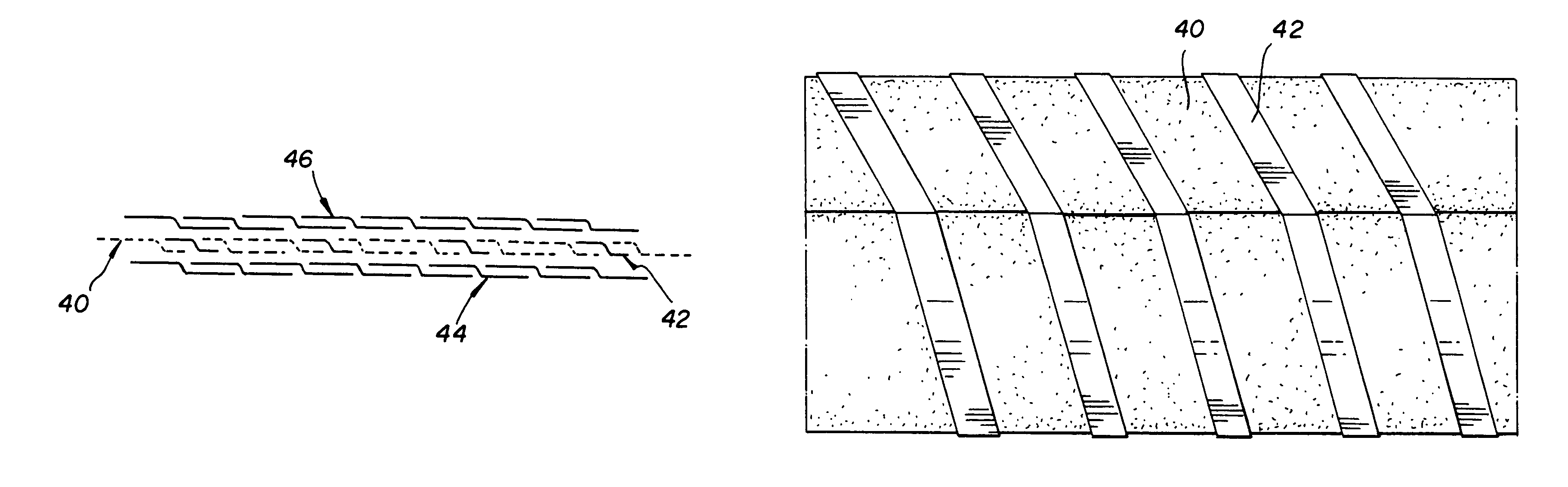
[0025]In one embodiment, the present invention provides insulating tapes for insulating an electrical conductor. The tapes comprise a groundwall layer, an inner conductive layer, an outer conductive layer, and a slip layer located between the two conductive layers. The slip layer itself comprises non-stick material coated porous glass tape. The slip layer allows for a difference of movement between the inner conductive layer and the outer conductive layer without damage to the insulating tape. Interwoven with the slip layers is a conductive interweave. The slip layer is wrapped around the electrical conductor in an overlapping manner that allows the conductive interweave to maintain contact between the inner conductive layer and the outer conductive layer. Also, the porosity of the slip layer is sufficient to allow an impregnation of a resin through the slip layer to the inner conductive layer

[0026]As used herein, the term non-stick material refers to all non-stick materials that ma...


PUM

PropertyMeasurementUnit
thicknessaaaaaaaaaa
movementaaaaaaaaaa
temperaturesaaaaaaaaaa

Abstract

A non-stick material coated glass slip layer for use in insulating tapes for electrical conductors. A conductive glass tape is interwoven with a non-stick material coated glass tape to form the slip layer. The slip layer is sandwiched between and inner conductive layer that is in contact with and electrical conductor, and an cater conductive layer that is in contact with machinery, such as a generator. The slip layer allows for a difference of movement between the inner conductive layer and the outer conductive layer without damage to the insulating tape.

Description

BACKGROUND[0001]With the use of any form of electrical appliance, there is a need to electrically insulate conductors. Conductors need to be wrapped in a insulating tape to prevent electric discharge. An example of this is shown in FIG. 1. Illustrated here is a coil 13, comprising a plurality of turns of conductors 14. Each turn of the conductor 14 consists essentially of a copper bar or wire wrapped with a turn insulation 15. The turn insulation 15 is prepared preferably from a fibrous sheet or strip which is typically impregnated with a resin. The turn insulation 15 may be not adequate alone to withstand the severe voltage gradients that will be present between the conductor and ground when the coil is installed in a high-voltage generator. Therefore, ground insulation for the coil is provided by wrapping one or more layers of composite mica tape 16 about the turn 14.[0002]Such a mica-tape 16 comprises a pliable backing sheet 18 of, for example, poly-ethylene glycol terephthalate ...

Claims


Application Information

Patent Timeline
Patent Type & Authority Patents(United States)
IPC IPC(8): H01B7/00B32B5/18B32B17/00H02K3/40
CPCB32B5/18B32B17/00H02K3/40B32B17/06Y10T442/2418Y10T442/3854B32B38/08B32B2260/046B32B2307/202
Inventor EMERY, F. TIM
Owner SIEMENS ENERGY INC
Learn More