
Transmission path controlling apparatus and transmission path controlling method as well as medium having transmission path controlling program recorded thereon

a technology of transmission path and transmission path, which is applied in the direction of data switching network, frequency-division multiplex, instruments, etc., can solve the problems of inability to cope with a variation of network load on a real time basis, inability to use unoccupied routes, and inability to control the transmission path

Inactive Publication Date: 2006-11-14
FUJITSU LTD
View PDF9 Cites 85 Cited by
  • Summary
  • Abstract
  • Description
  • Claims
  • Application Information

AI Technical Summary

Benefits of technology

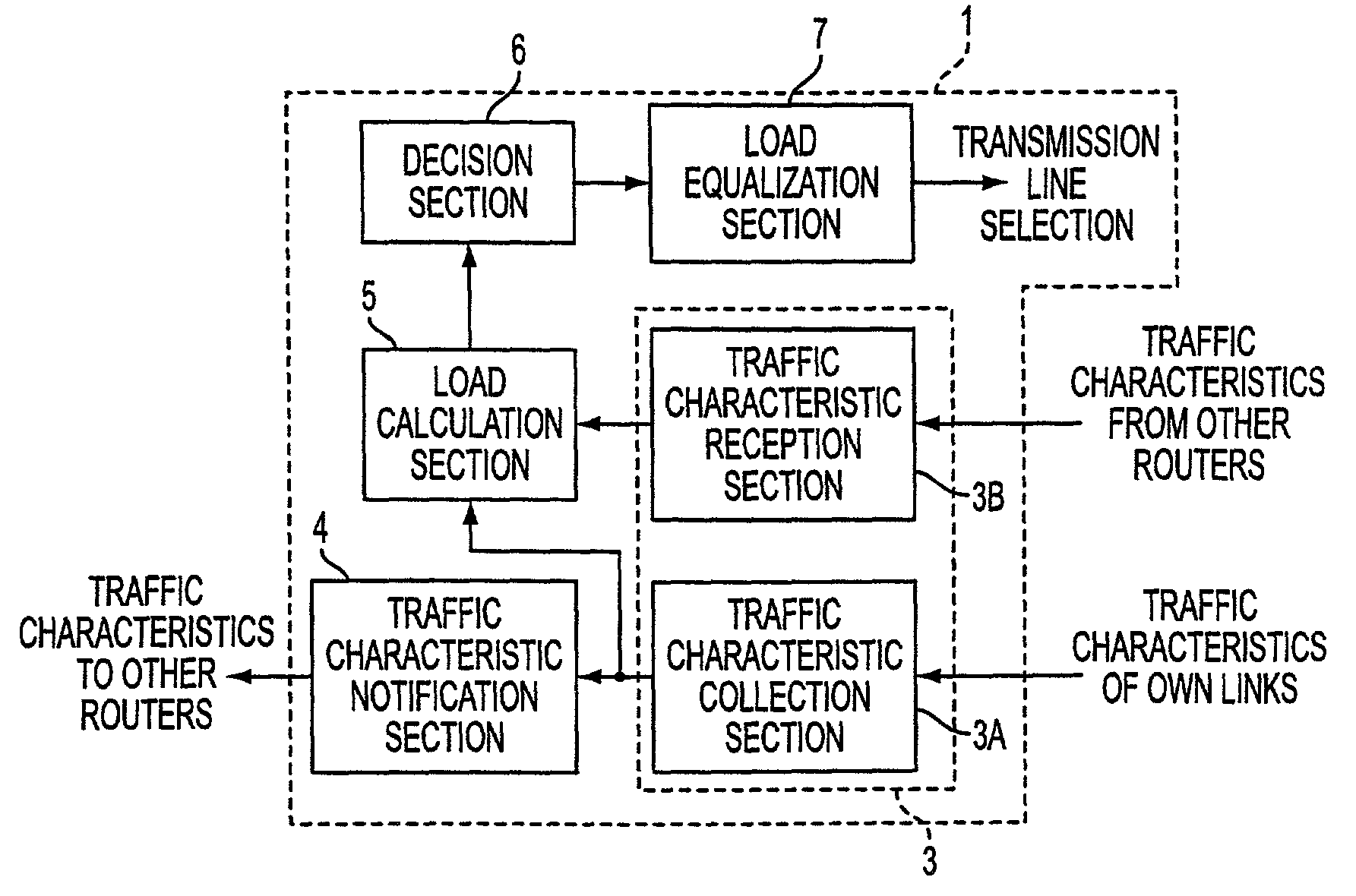
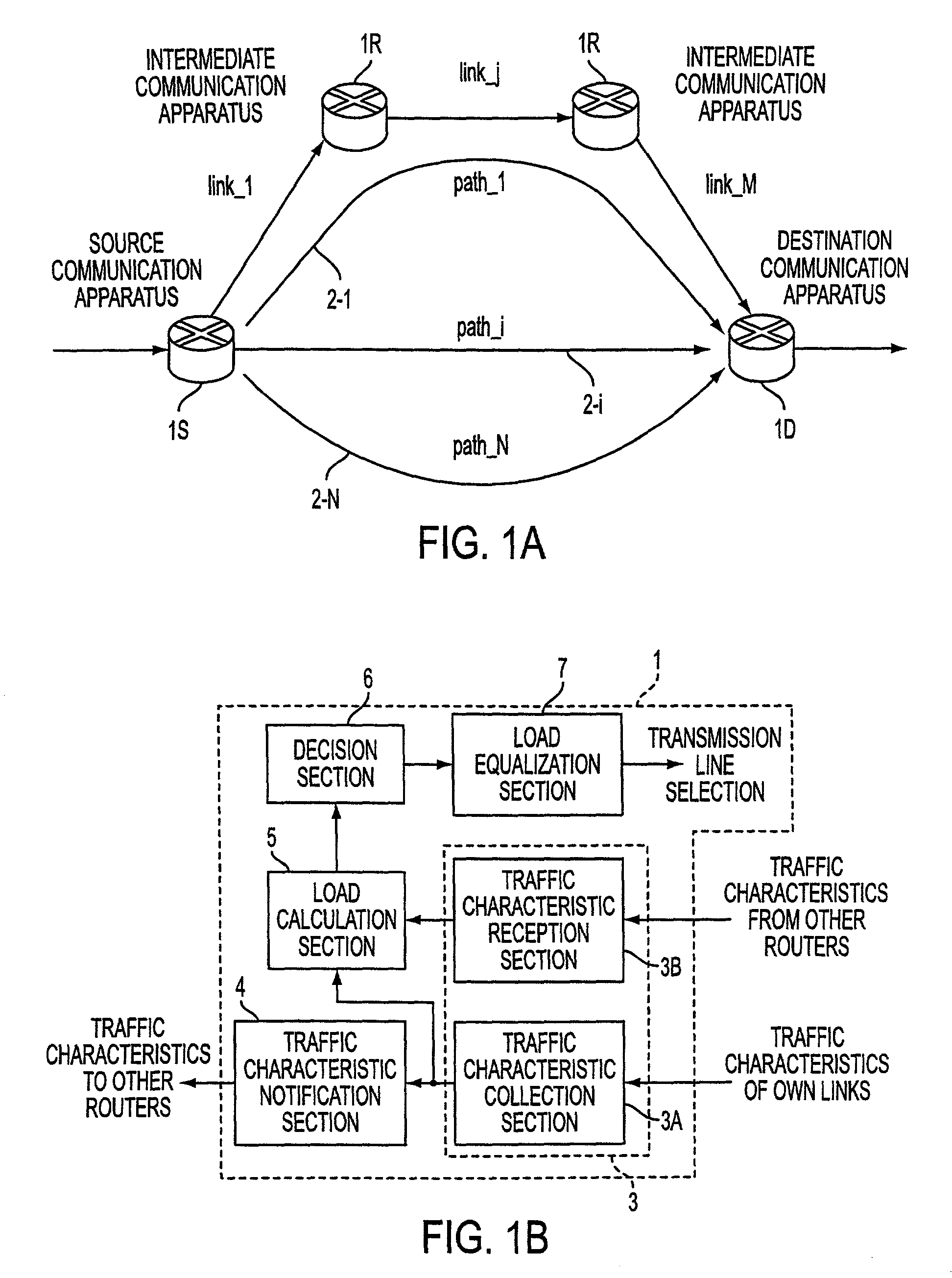
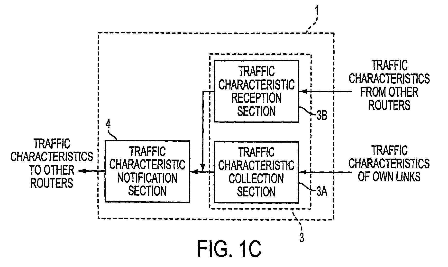
The present invention provides a transmission path controlling apparatus and method for controlling transmission paths in a network, such as the Internet, that can distribute load among multiple routes to avoid network congestion and traffic engineering issues. The apparatus includes a traffic characteristic collection section, a traffic characteristic notification section, a load calculation section, a decision section, and a load equalization section. The apparatus can be used in various network topologies and can be expanded to include additional routes based on the traffic characteristics. The technical effect of the invention is to provide a more efficient and effective way to control transmission paths in networks, regardless of the network topology or type of transmission paths.

Problems solved by technology

However, the routing protocol mentioned has a problem in that a plurality of routes to a destination cannot be selected or the routing protocol is executed only when the network topology varies.
In short, with such a technique as described above, once a route is established, an IP packet is transferred only along the route, and as a result, there is the possibility that chronic congestion occurs.
Further, such a technique as described above has a problem also in that, since a plurality of routes cannot be set, when a certain route suffers from congestion, even if some other route is unoccupied, this unoccupied route cannot be used.
However, the method which uses a function of the OSPF according to (1-1) above has the following problems.
Further, since the OSPF is used, the method cannot cope with a variation of the network load on a real time basis.
Also the method which uses a function of the IBGP according to (1-2) above has a restriction in that the multipaths must be equal in cost and has a problem in that the degree of freedom in path selection is low, similarly to the problems of the method which uses a function of the OSPF.
With the technique, however, even if a traffic balance can be provided between networks, load distribution in each network cannot be performed.
Further, only load distribution in the layer 3 and in a unit of a route is taken into consideration, and there is the possibility that load distribution control may be complicated.

Method used


Image

  • Transmission path controlling apparatus and transmission path controlling method as well as medium having transmission path controlling program recorded thereon
  • Transmission path controlling apparatus and transmission path controlling method as well as medium having transmission path controlling program recorded thereon
  • Transmission path controlling apparatus and transmission path controlling method as well as medium having transmission path controlling program recorded thereon

Examples


example 1

(A) CALCULATION EXAMPLE 1

[0248]If it is assumed that the logical bandwidths LBW [bit / s] of the paths 1, 2 and 3 are 10 M, 8 M and 2 M, respectively, and the effective loads ρ effective are 0.5, 0.2 and 0.3, respectively, then the actual traffics [bit / s] of the paths 1, 2 and 3 are 10 M×0.5=5 M, 8 M×0.2=1.6 M, and 2 M×0.3=0.6 M, respectively.

[0249]Further, if all paths in this instance are regarded as one virtual pipe, then an average utilization ρ ave effective is determined in the following manner.

ρave effective=(5 M+1.6 M+0.6 M) / (10 M+8 M+2 M)=0.36

[0250]Then, if the effective bandwidth (EBW) [bit / s] to be moved is calculated for the paths 1, 2 and 3, then the following results are obtained.

[0251]In particular, the effective bandwidth ΔEBW PATH1 to be moved of the path 1 is (0.36−0.5)×10 M=−1.4 M; the effective bandwidth ΔEBW PATH2 to be moved of the path 2 is (0.36−0.2)×8 M=+1.28 M; and the effective bandwidth ΔEBW PATH3 to be moved of the path 3 is (0.36−0.3)×2 M=+0.12 M. Then, i...

example 2

(B) CALCULATION EXAMPLE 2

[0254]If it is assumed that the logical bandwidths LBW [bit / s] of the paths 1, 2, 3 and 4 are 150 M, 45 M, 150 M and 600 M, respectively, and further the effective loads ρ effective are 1.2, 1.5, 1.1 and 0.8, respectively, then the actual traffics [bit / s] of the paths 1, 2, 3 and 4 are 150 M ×1.2=180 M, 45 M×1.5=67.5 M, 150 M×1.1=165 M, and 600 M×0.8=480 M, respectively.

[0255]Further, if all paths are regarded as one virtual pipe, then an average utilization pave effective is determined in the following manner.

ρ ave effective=(180 M+67.5 M+165 M+480 M) / (150 M+45 M+150 M+600 M)=892.5 / 945=0.94

[0256]Then, if the effective bandwidth (EBW) to be moved is calculated for all of the paths 1 to 4, then the following results are obtained.

[0257]In particular, the effective bandwidth ΔEBW PATH1 to be moved of the path 1 is (0.94−1.2)×150 M=−39 M; the effective bandwidth ΔEBW PATH2 to be moved of the path 2 is (0.94−1.5)×45 M=−25.2 M; the effective bandwidth ΔEBW PATH3 t...


PUM


Abstract

The present invention relates to distributing the load between the set routes among a plurality of routes between a communication apparatus which serves as a start point to another communication apparatus which serves as an end point. An apparatus provided in a router in a network collects traffic characteristics of transmission paths connected to the router, notifies other routers of the collected traffic characteristics, calculates load based on the collected traffic characteristics, decides based on the calculated load information whether or not a transmission path should be added or deleted, and equalizes the load among the plurality of transmission paths.

Description

BACKGROUND OF THE INVENTION[0001]1. Field of the Invention[0002]This invention relates to a transmission path controlling apparatus provided in a communication apparatus (for example, a router or load equalization apparatus) which forms an network, and further to a transmission path controlling method executed by the apparatus as well as a medium on which a transmission path controlling program used in the apparatus is recorded. The method and apparatus may be provided within, for example, an Internet Protocol network (in the following description an Internet Protocol is sometimes referred to simply as IP; accordingly, an Internet Protocol network is referred to simply as IP network).[0003]2. Description of the Related Art[0004]The Internet is intended to handle all communication applications on the internet protocol and is being popularized rapidly at present. Further, the Internet originally has a connectionless network architecture which does not involve establishment of a connec...

Claims


Application Information

Patent Timeline
Patent Type & Authority Patents(United States)
IPC IPC(8): H04J3/16H04L45/243
CPCH04L45/00H04L45/24H04L47/10H04L47/11H04L47/125H04L12/2602H04L43/00H04L43/045H04L43/0829H04L43/0876
Inventor SOUMIYA, TOSHIONAKAMICHI, KOJITAKASHIMA, KENYA
Owner FUJITSU LTD
Learn More