Adaptive threshold based jitter buffer management for packetized data

a buffer management and threshold technology, applied in the field of telecommunications, can solve the problems of network delay and jitter characteristics that may change rapidly, and achieve the effect of reducing playout delay

Inactive Publication Date: 2006-07-18
INTEL CORP
View PDF9 Cites 52 Cited by
  • Summary
  • Abstract
  • Description
  • Claims
  • Application Information

AI Technical Summary

Benefits of technology

[0008]Observed network delay and jitter characteristics may change rapidly over time as other connections are set up and taken down in the network. Thus, a jitter buffering method is desirable that can (i) control jitter buffer underflows/overflows at

Problems solved by technology

Observed network delay and jitter characteristics may change rapidly o

Method used


Image

  • Adaptive threshold based jitter buffer management for packetized data
  • Adaptive threshold based jitter buffer management for packetized data
  • Adaptive threshold based jitter buffer management for packetized data

Examples


Embodiment Construction

[0022]Reference herein to “one embodiment” or “an embodiment” means that a particular feature, structure, or characteristic described in connection with the embodiment can be included in at least one embodiment of the invention. The appearances of the phrase “in one embodiment” in various places in the specification are not necessarily all referring to the same embodiment, nor are separate or alternative embodiments mutually exclusive of other embodiments. The description herein is largely based on a particular jitter buffer for playing out real-time audio data. Those skilled in the art can appreciate that the description can be equally applied to other jitter buffers and / or other types of real-time data.

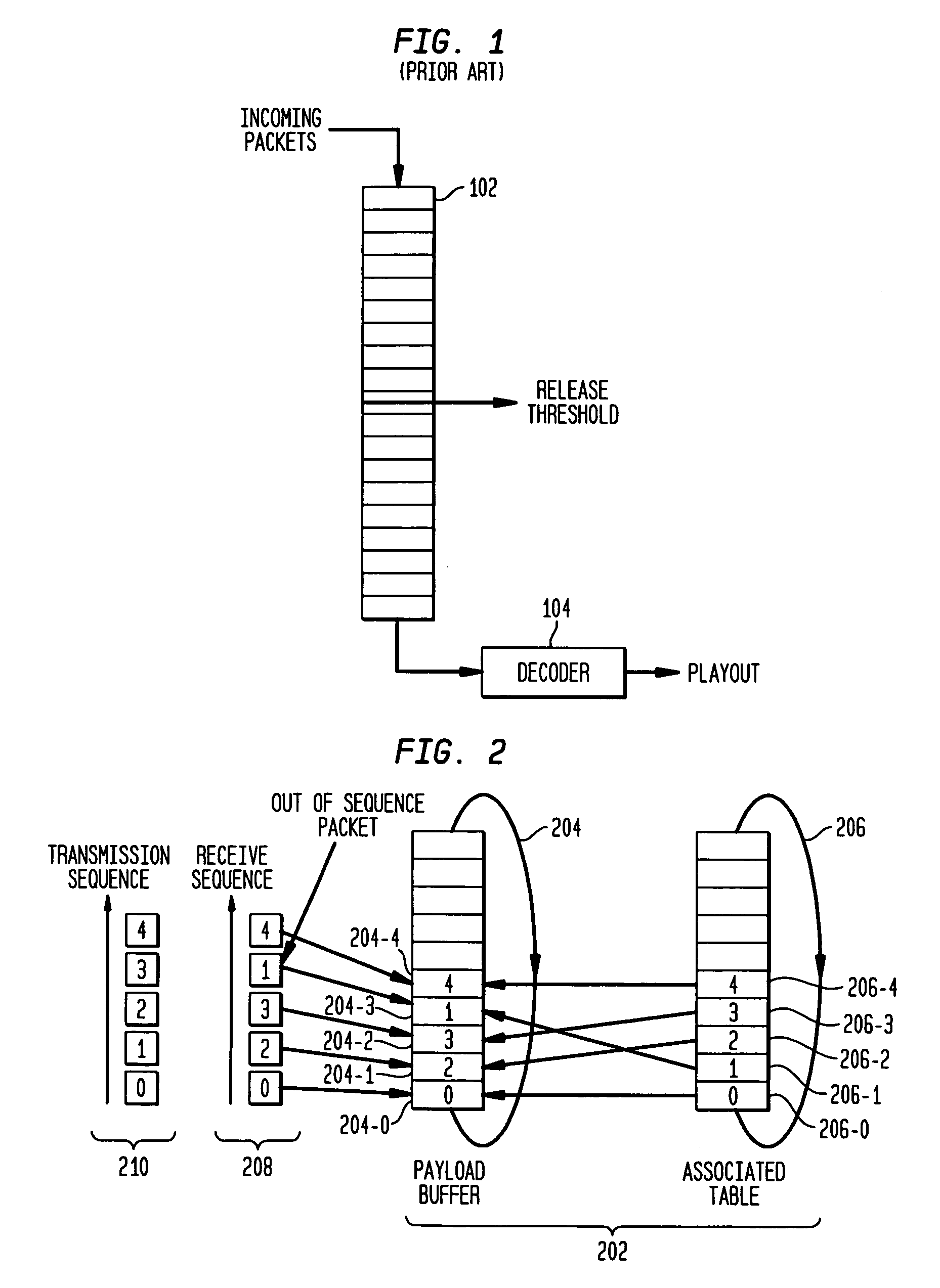
[0023]FIG. 2 shows a diagram of a jitter buffer 202 according to one embodiment of the present invention. Jitter buffer 202 comprises a first circular buffer 204 (payload buffer) and a second circular buffer 206 (associated table). In one embodiment, buffer 204 is configured to stor...


PUM


Abstract

Adaptive jitter buffer management, e.g., for playout of packetized data transmitted over a network. Playout delay is iteratively adjusted based on changing network traffic characteristics by varying the release threshold in a jitter buffer. The adjustment is carried out by evaluating three quantities: (1) average packet transit time over the network; (2) jitter of the packet transit time; and (3) additional waiting time due to the presence of out-of-sequence packets. This invention reduces negative effects of jitter and/or transmission irregularities, such as late arrival of packets and out-of-sequence packets, while maintaining relatively low playout delay and relatively high quality of service.

Description

BACKGROUND OF THE INVENTION[0001]1. Field of the Invention[0002]The present invention relates to the field of telecommunications and, more specifically, to managing real-time data packet receipt and playout in the presence of variable packet delays.[0003]2. Description of the Related Art[0004]Real-time digital audio for Internet telephony and playback for World Wide Web browsers employs packetized audio data that is transferred over a network. Each packet contains information that allows the data network to route it to the appropriate destination. Packets from many different transmitters travel sequentially over single connections between routing points (nodes), and packets from the same transmitter (source) may travel different paths through nodes of the network. Consequently, each packet in a sequence of packets from a specific source to a specific receiver (destination) may experience a different delay as it travels through its path through the network. Delay variation also occur...

Claims


Application Information

Patent Timeline
IPC IPC(8): H04L12/24H04L12/64H04L29/06H04M7/00
CPCH04L12/6418H04L29/06027H04L65/80H04L2012/6489H04M7/006H04L2012/6481H04L65/1101
Inventor COLAVITO, LEONARD RAYMONDJIN, LIANGKINNEY, KEVIN R.WANG, RONG
Owner INTEL CORP
Why Eureka
Try Eureka