Gas turbine airfoil leading edge cooling

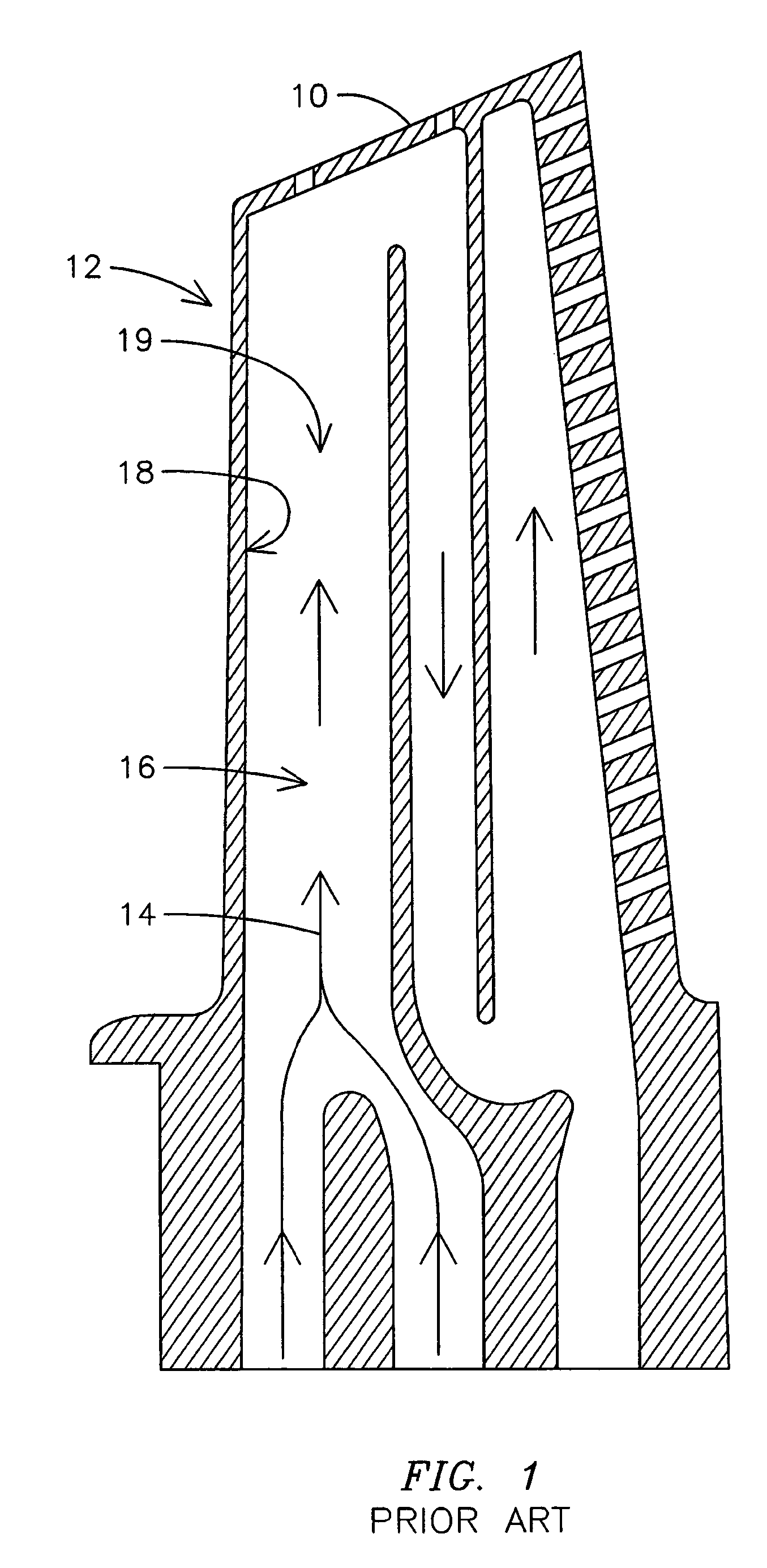
a gas turbine and airfoil technology, applied in the direction of machines/engines, marine propulsion, vessel construction, etc., can solve the problems of reducing the overall efficiency of the gas turbine, the distribution and velocity of cooling fluid flow , /b> to the leading edge backside portion b>18/b> of the airfoil,

Inactive Publication Date: 2006-11-21
SIEMENS ENERGY INC
View PDF23 Cites 24 Cited by
  • Summary
  • Abstract
  • Description
  • Claims
  • Application Information

AI Technical Summary

Problems solved by technology

While such cooling configurations may be effective for cooling airfoils, diverting any portion of air from the compressor to provide a cooling fluid flow decreases the overall efficiency of the gas turbine.
One problem with such as design is that a distribution and velocity of the cooling fluid flow 14 to a leading edge backside portion 18 of the airfoil is decreased compared to the distribution and velocity in a central portion 19 of the cooling channel 16.
Increased cooling flow may alleviate this problem, but at the cost of reduced efficiency.

Method used


Image

  • Gas turbine airfoil leading edge cooling
  • Gas turbine airfoil leading edge cooling
  • Gas turbine airfoil leading edge cooling

Examples


Embodiment Construction

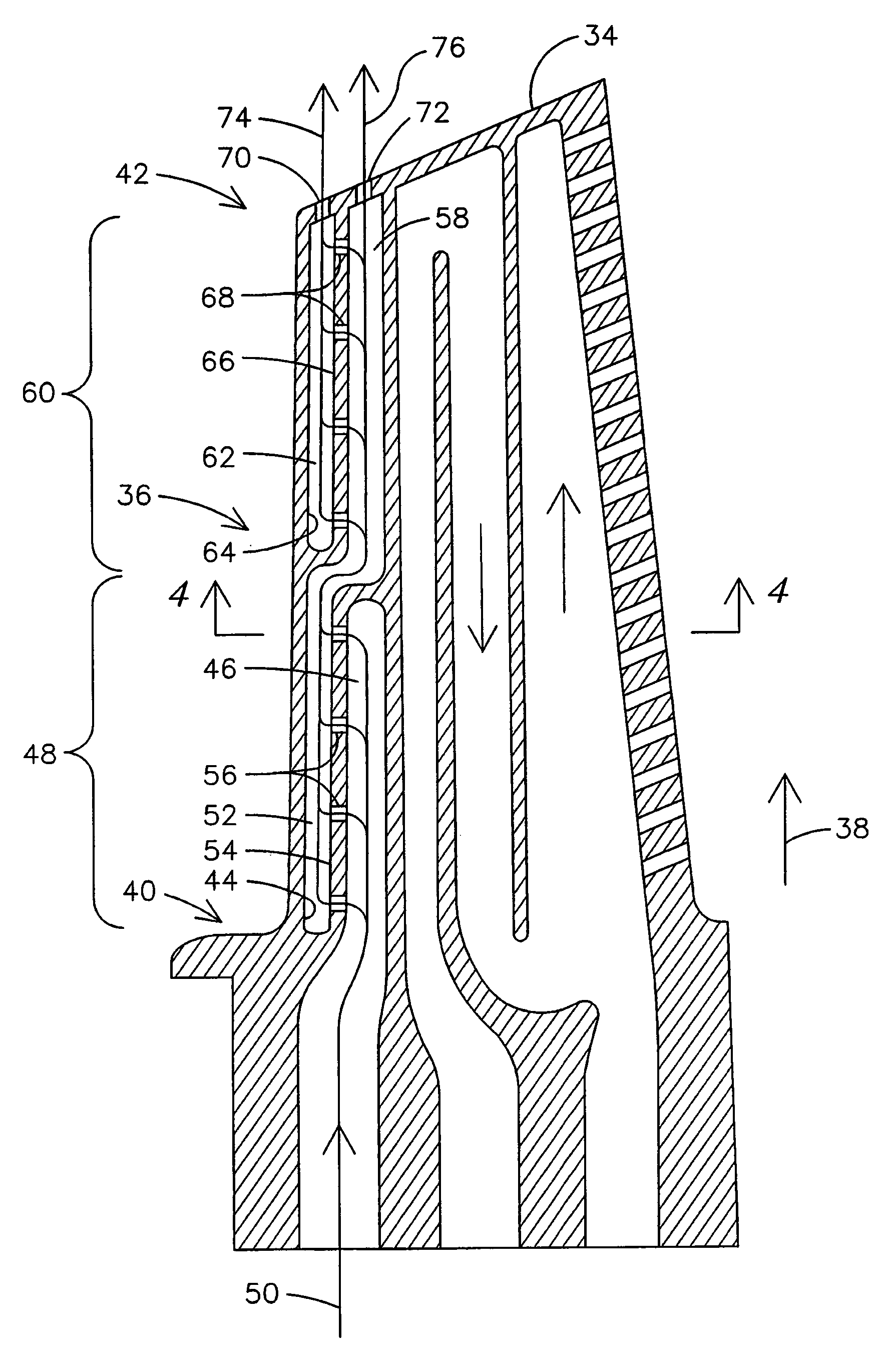
[0011]The inventor of the present invention has developed an improved cooled gas turbine airfoil having an innovative leading edge cooling scheme that may be used with reduced cooling fluid flows compared to conventional techniques. FIG. 3 is a cross sectional view of an embodiment of the gas turbine airfoil 34, while FIG. 4 shows a cross sectional view of the gas turbine airfoil of FIG. 3 taken along line A—A. Generally, the airfoil 34 includes a leading edge portion 36 extending in a radial direction 38 from a root 40 to a tip 42 of the airfoil 34. Within the leading edge portion 36, a series of fluidically interconnected chambers are provided. The interconnected chambers are configured to supply a cooling fluid flow, impinge the cooling fluid flow against a backside 44 of the leading edge portion 36, and collect the cooling fluid flow after impingement.

[0012]To achieve improved leading edge cooling, a cooling fluid supply chamber 46 may be disposed within a first section 48 of th...


PUM


Abstract

A gas turbine airfoil (34) includes sequentially connected, radially displaced chambers (e.g., 46, 58) within the airfoil. A cooling fluid supply chamber (46) is disposed within a first section (48) of a leading edge portion (36) of the airfoil and receives a cooling fluid flow (50). The cooling fluid supply chamber is in fluid communication with a first leading edge impingement chamber (52) disposed against a backside (44) of the leading edge portion. A discharge chamber (58) in serial fluid communication with the first impingement chamber is disposed radially outward of the first impingement chamber and within a second section (60) of the leading edge portion. A second leading edge impingement chamber (62) in fluid communication with the discharge chamber is disposed against a backside (64) of the leading edge portion in the second section. The chambers may be arranged to limit centrifugal force-induced pressure buildup in the respective chambers.

Description

FIELD OF THE INVENTION[0001]This invention relates generally to gas turbines engines, and, in particular, to cooling of gas turbine airfoils.BACKGROUND OF THE INVENTION[0002]Gas turbine airfoils exposed to hot combustion gases have been cooled by forming passageways within the airfoil and passing a cooling fluid through the passageways to convectively cool the airfoil. The cooling fluid may include compressed air bled from a compressor of the gas turbine. Such cooled airfoils may include a serpentine, multiple-pass flow path to provide sufficient convective cooling to maintain all portions of the airfoil at a relatively uniform temperature. While such cooling configurations may be effective for cooling airfoils, diverting any portion of air from the compressor to provide a cooling fluid flow decreases the overall efficiency of the gas turbine. Accordingly, it is desired to minimize the amount of compressed air bled from the compressor while attempting to achieve sufficient cooling o...

Claims


Application Information

Patent Timeline
Patent Type & Authority Patents(United States)
IPC IPC(8): F01D5/08F01D5/18B63H1/00
CPCF01D5/187F05D2260/201
Inventor LIANG, GEORGE
Owner SIEMENS ENERGY INC
Why Eureka
Try Eureka