Rotating wheel return mechanism

a return mechanism and rotating wheel technology, applied in the field of baseball or softball practice systems, can solve the problems of lack of certain features of the machine that provides a more versatile and comprehensive training system, and the dangerous environment of the machine, so as to promote efficiency

Inactive Publication Date: 2006-11-21
GRAND SLAM SPORTS
View PDF20 Cites 9 Cited by
  • Summary
  • Abstract
  • Description
  • Claims
  • Application Information

AI Technical Summary

Benefits of technology

[0005]Accordingly, it is an aspect of the present invention to provide a practice machine that offers an expansive, flexible training system, which promotes efficiency during a practice session.
[0011]It is another aspect of the present invention to provide a practice machine that includes safety mechanisms for reducing the risk of accidents or injury.
[0012]Accordingly, a practice machine for receiving a thrown ball and returning it to a user is provided with a backstop for stopping the thrown ball, a pan disposed below the backstop for collecting the ball, a ball return adjacent the backstop for expelling the ball, and a trough disposed between the pan and the ball return for feeding the ball from the pan to the ball return. The machine may include an electro-mechanical stop affixed to the trough for obstructing the ball before it enters the ball return. The stop can be deployed by a proximity sensor, which detects motion within a specified danger zone, preventing the ball from being expelled from the machine. A danger zone control may be provided for adjusting the perimeter of the danger zone. Optionally, the danger zone control is tamper resistant.
[0019]Yet another aspect of the present invention is to provide a practice machine that is conveniently stowable or easily portable from one practice location to another.
[0020]Accordingly, a backstop for stopping a thrown ball is provided having a collapsible frame and netting. The frame may include a plurality of collapsible upright support posts. Each upright support post may have a plurality of telescoping tubular members. Each telescoping tubular member may be capable of extending substantially end-to-end in an elongated configuration. Moreover, each telescoping tubular member may be capable of collapsing, one inside the next, in a collapsed configuration. The netting can be secured to the frame for providing a target for receiving the thrown ball. The netting may be formed from flexible material capable of collapsing with the frame. The backstop can be collapsible from a fully expanded target configuration when the plurality of telescoping tubular members are in the elongated configuration to a compact transportable configuration when the plurality of telescoping tubular members are in the collapsed configuration.

Problems solved by technology

However, these machines furnish a dangerous practice environment, particularly to unsupervised children, whom are playing in the general vicinity of the machine or are actively using the device.
Moreover, machines of this design lack certain features that provide a more versatile and comprehensive training system.

Method used


Image

  • Rotating wheel return mechanism
  • Rotating wheel return mechanism
  • Rotating wheel return mechanism

Examples


Embodiment Construction

)

[0035]As required, detailed embodiments of the present invention are disclosed herein. However, it is to be understood that the disclosed embodiments are merely exemplary of an invention that may be embodied in various and alternative forms. Therefore, specific functional details disclosed herein are not to be interpreted as limiting, but merely as a representative basis for the claims and / or as a representative basis for teaching one skilled in the art to variously employ the present invention.

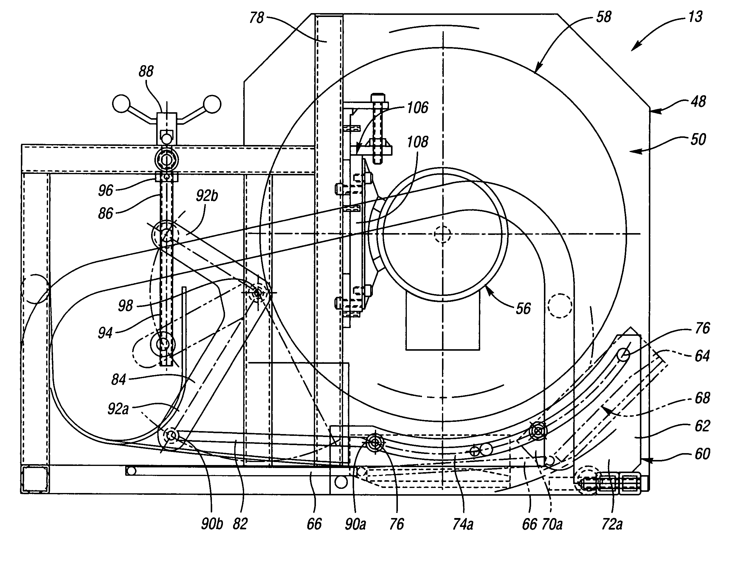
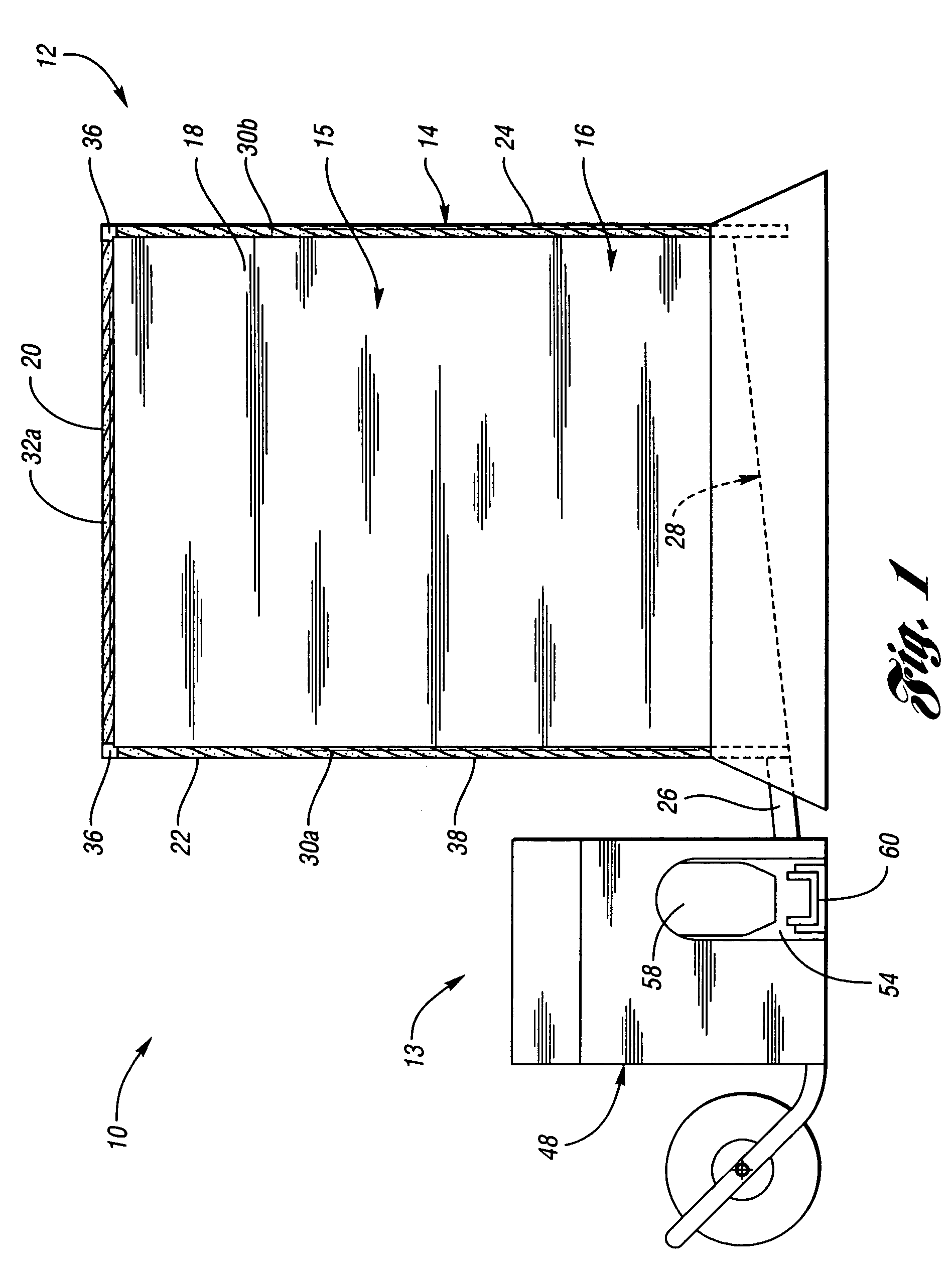
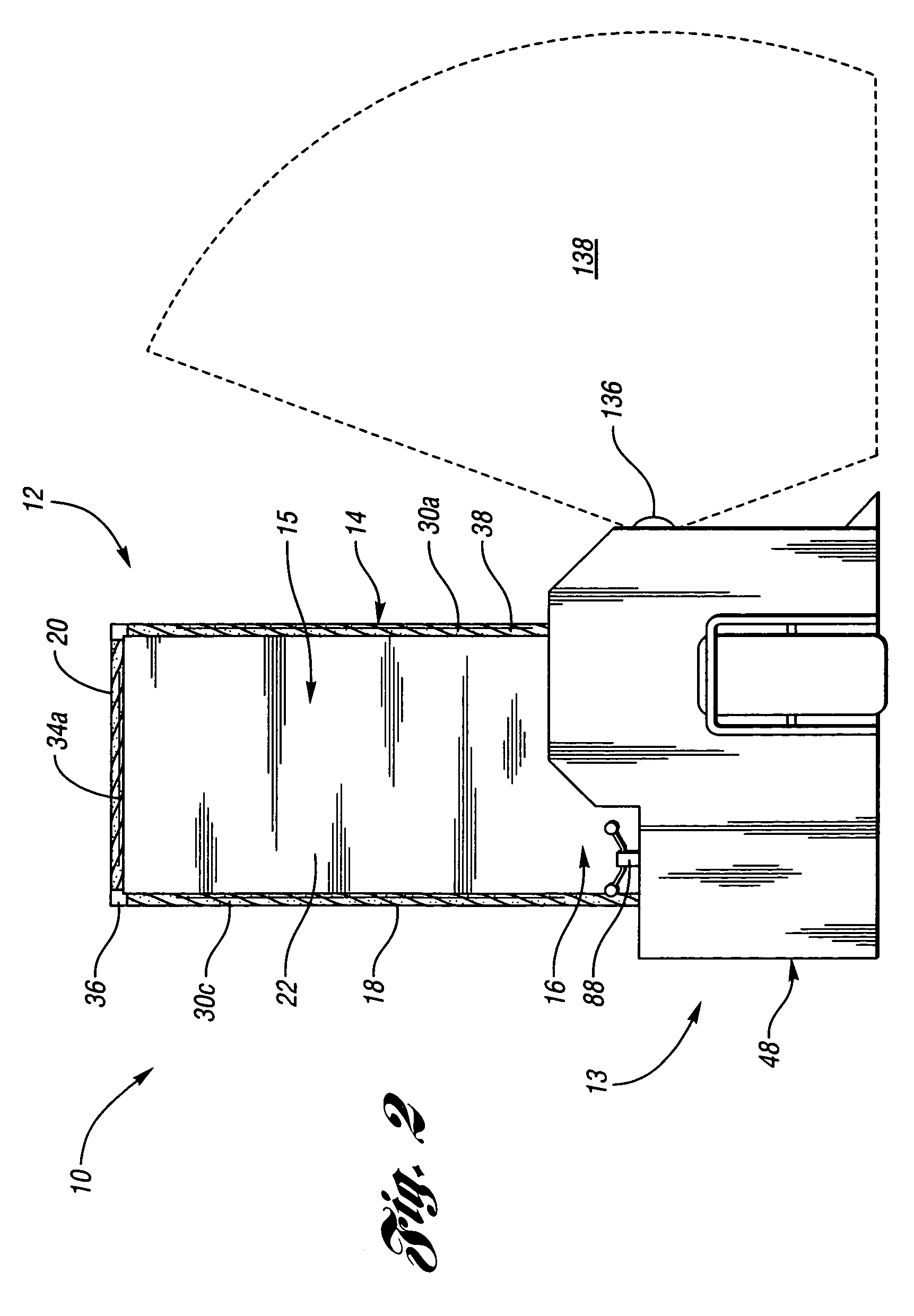
[0036]A practice machine 10 for receiving a thrown ball and returning it to a user is illustrated in FIGS. 1–4. The practice machine 10 includes a backstop 12 and a ball return 13, as shown in FIGS. 1–3. The backstop 12 has two main components: a frame 14 defining a ball receiving chamber 15 and netting 16. The netting 16 provides a back wall 18, a roof 20, a left side wall 22 and a right side wall 24 for generally enclosing the ball receiving chamber 15, leaving a substantially open area fo...


PUM


Abstract

A practice machine for receiving a thrown ball and returning it to a user is generally provided with a backstop for stopping the thrown ball, a pan disposed below the backstop for collecting the ball, a ball return adjacent the backstop for expelling the ball, and a trough disposed between the pan and the ball return for feeding the ball from the pan to the ball return. The ball return can adjust between ball sizes and vary the trajectory of expelled balls. Moreover, the ball return can be equipped with safety features including a proximity sensor, audible alerts, speed adjustment and tamper resistant controls. Further, the ball return can alternate between a MANUAL mode and an AUTOMATIC mode. The backstop of the practice machine can be collapsible to permit convenient storage and ease of transportation.

Description

BACKGROUND OF THE INVENTION[0001]1. Field of the Invention[0002]The present invention relates to a baseball or softball practice system and, more particularly, to a portable system for receiving a thrown ball and safely returning it to a user.[0003]2. Background Art[0004]Over the years, a wide variety of ball receipt and return machines have been developed for enhancing the defensive skills of baseball or softball players. A representative sample of such machines are illustrated in U.S. Pat. Nos. 4,883,272, 5,133,548, and 5,573,239. These devices typically have a rectangular frame for supporting a backstop, which provides a general throwing target. The backstop is frequently a net or tarp the sustaining the impact of thrown ball and allowing it to drop directly into a pan positioned below the target backstop. Often, machines of this variety are affixed with a feeding apparatus that delivers the ball to a return mechanism, which expels the ball into the general direction of the user....

Claims


Application Information

Patent Timeline
Patent Type & Authority Patents(United States)
IPC IPC(8): A63B69/00
CPCA63B47/025A63B69/0097A63B69/406A63B71/022A63B2208/12A63B2210/50
Inventor KTSON, JAMES A.ALLOR, FREDERICK M.
Owner GRAND SLAM SPORTS
Why Eureka
Try Eureka