Battery with proportional collectors, straps, and plates

Inactive Publication Date: 2006-11-21
PANASONIC CORP
View PDF9 Cites 1 Cited by
  • Summary
  • Abstract
  • Description
  • Claims
  • Application Information

AI Technical Summary

Benefits of technology

[0061]Thus, the invention described herein makes possible the advantages of providing: (1) a battery comprising a plurality of linked cells, in which each has a high level of cooling efficiency, cost for cooling each cell is low, and substantially no variation occurs in the life of each cell; (2) a battery, in which a battery case containing cells can be positioned with respect to a lid, and it is possible to prevent heat generation around terminals; and (3) a battery, in which the weight of the battery can be reduced while preventing damage, such as rupture, of a collector, and the width direction lengths of a strap and a collector can be appropriately adjusted so as to prevent voltage drop due to the increased high resistance of the strap.

Problems solved by technology

For such a cell, when the ambient temperature is high or a large amount of current is discharged, heat is not sufficiently dissipated from the electrode plates contained in each cell, causing the temperature of the cell to be increased, potentially leading to a reduction in the life of the battery.
For this reason, the configuration of the entire battery is complicated and therefore the number of assembling steps is increased, causing an increase in cost.
Therefore, when a great load is applied to the battery and therefore the amount of heat generated is great, it is difficult to obtain a sufficient cooling effect.
As in Japanese Laid-Open Publication No. 2000-164186, the configuration of the entire battery is complicated and therefore the number of assembling steps is increased, causing an increase in cost.
However, in this configuration, the coolant is allowed to flow mainly along the thickness direction side and therefore a sufficient level of cooling efficiency cannot be obtained.
If the pressure acting on the electrode plate becomes small, the distance between adjacent electrode plates becomes great, causing the electrolytic solution to splash so that the electrolytic solution is likely to be dried up.
Despite this configuration, the expansion of the cells 401 and 406 provided on the ends of the battery cannot be sufficiently suppressed.
However, in these publications, the lid is attached to the bath containing the cells, although positioning means for attaching the lid to an appropriate position is not provided.
Therefore, it is not easy to appropriately position the lid with respect to the bath.
If the lid is not correctly positioned with respect to the bath, the cells are not effectively cooled by the coolant.
Also, when the battery is used in a situation where wobble or the like may occur, the lid is displaced from the bath, whereby the coolant is likely to penetrate into the power generation element.
In particular, when a terminal portion, which is externally connected, excessively generates heat, a portion around the terminal of the bath containing the cells may be melted.
However, in the above-described publications, the electrode plate is mainly cooled by the coolant, but the battery is not provided with an arrangement for preventing the heat generation of the terminal portion.
Next, a problem with the internal structure of conventional batteries having a configuration in which positive electrode plates and negative electrode plates are laminated via separators will be described below.

Method used


Image

  • Battery with proportional collectors, straps, and plates
  • Battery with proportional collectors, straps, and plates
  • Battery with proportional collectors, straps, and plates

Examples


example 1

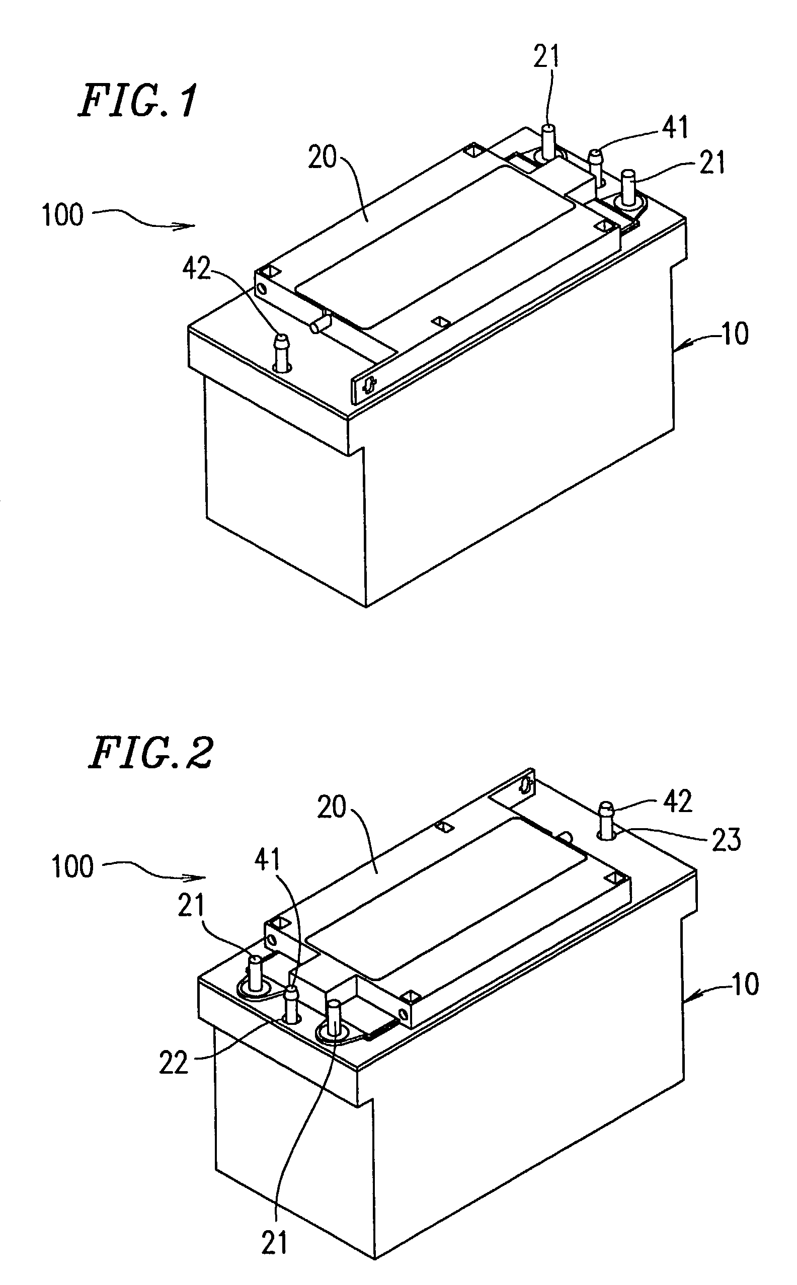
[0113]FIG. 1 is a perspective view showing a battery 100 according to Example 1 of the present invention, when viewed in a slanted direction from the front. FIG. 2 is a perspective view showing the battery 100, when viewed in a slanted direction from the rear. The battery 100 contains a plurality of cells. The cells are cooled with high cooling efficiency. The battery 100 comprises a cooling box 10 for cooling the cells and a lid 20 for sealing the cooling box 10. The cooling box 10 and the lid 20 are made of a synthetic resin.

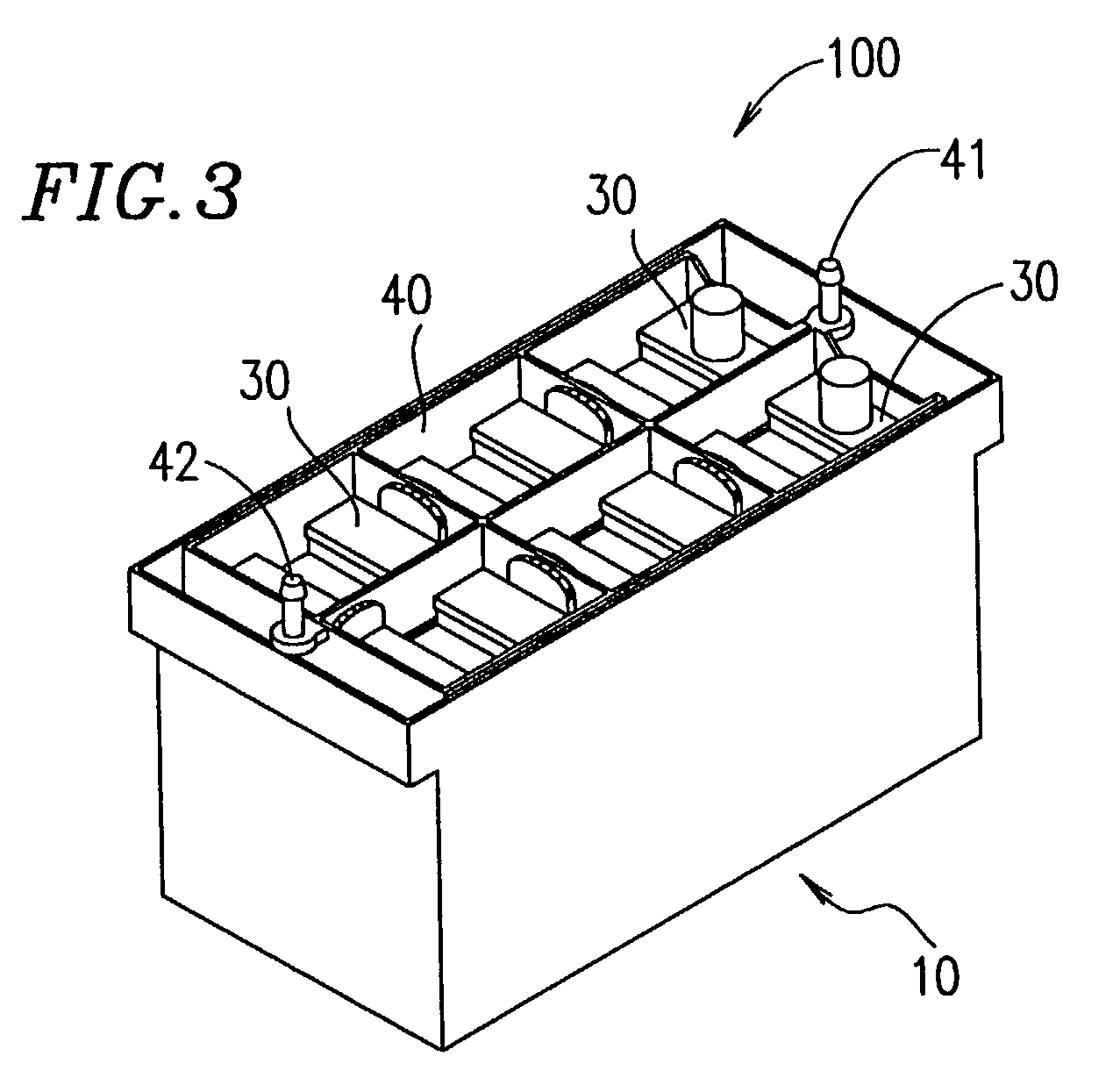
[0114]FIG. 3 is a perspective view showing a battery 100 (note that the lid 20 is removed from the cooling box 10). In the cooling box 10, 6 cells 30, which are arranged in a matrix of 3 rows×2 columns and connected in series, are integrally contained in a frame-like battery case 40. The battery case 40 is made of a synthetic resin. The battery case 40 is provided with an inlet orifice 41 and an outlet orifice 42, through which cooling water, which is a coolan...

example 2

[0158]FIG. 36 is a perspective view showing a battery according to Example 2 of the present invention.

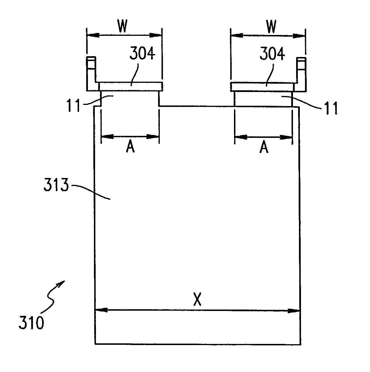
[0159]A battery 301 according to Example 2 of the present invention has a case body 302 in the shape of a hollow rectangular parallelepiped having an open top. The inner space of the case body 302 is divided with a partition 303 into first to sixth cells 302a to 302f. Specifically, the inner space of the case body 302 is divided into three portions in the longitudinal direction and into two portions in the width direction, forming the 6 cells 302a to 302f. The cells 302a to 302f each have a cross section in the shape of a rectangle elongated in the longitudinal direction of the case body 302.

[0160]The cells 302a to 302f each comprise a unit power generation element containing a plurality of positive electrode plates (e.g., PbO2 plates) having a similar planar shape and a plurality of negative electrode plates (e.g., Pb plates) having a similar planar shape. In the unit power generat...


PUM


Abstract

A battery comprises at least four cells each comprising a bath in the shape of a rectangular parallelepiped having a width direction dimension greater than a thickness direction dimension, and a power generation element, the power generation element being contained in the bath, the thickness direction sides of the cells facing each other, and the width direction sides of the cells being arranged side by side. A coolant for cooling the cells is allowed to flow along the width direction sides of the cells.

Description

BACKGROUND OF THE INVENTION[0001]1. Field of the Invention[0002]The present invention relates to a battery and, more particularly, to a battery in which a plurality of cells are linked so as to obtain a required power capacity.[0003]2. Description of the Related Art[0004]Large-capacity batteries comprising a plurality of linked cells, such as nickel-cadmium cells, nickel-hydrogen cells, or hydrogen cells, are used in various electric appliances, electric vehicles, and the like. In such a large-capacity battery, typically, a plurality of cells in the shape of a thin rectangular parallelepiped are arranged close to each other and bound together. In each cell, a plurality of positive electrode plates and a plurality of negative electrode plates are alternately laminated via separators containing electrolytic solution. For such a cell, when the ambient temperature is high or a large amount of current is discharged, heat is not sufficiently dissipated from the electrode plates contained ...

Claims


Application Information

Patent Timeline
IPC IPC(8): H01M10/50H01M2/18H01M4/00H01M4/02H01M4/64H01M10/04H01M50/209H01M50/528
CPCH01M2/1061H01M10/0436H01M10/5004H01M10/5032H01M10/5046H01M10/5059H01M10/647H01M10/6551H01M10/6557H01M10/613Y02E60/10H01M50/209Y02P70/50
Inventor ANDO, KAZUNARIHIRAMATSU, AKITOSHIKIMURA, KENJI
Owner PANASONIC CORP
Why Eureka
Try Eureka