Ring generator

a generator and ring technology, applied in the direction of machines/engines, mechanical equipment, liquid fuel engines, etc., can solve the problem of increasing the temperature of the stator

Inactive Publication Date: 2011-10-27
WOBBEN ALOYS
View PDF12 Cites 13 Cited by
  • Summary
  • Abstract
  • Description
  • Claims
  • Application Information

AI Technical Summary

Benefits of technology

[0045]Preferably, in some embodiments, a wind power installation is characterized in that the ring generator is arranged within the pod except for an outer portion of the stator ring and the outer portion of the stator ring is arranged outside the pod to receive the afflux flow of wind. The pod also includes the hub casing which rotates with the rotor assembly in operation of the wind power installation. The hub casing is also referred to as the spinner. In that way the ring generator is substantially in the pod and is accordingly substantially protected from the influences of the weather. Cooling of the ring generator can already be achieved passively or actively within the pod for example by means of cooling passages and / or by using a suitable stator bell. It is additionally proposed that an outer portion of the stator ring is arranged in particular with a passive cooling region, outside the pod. In particular that affords a ring portion which projects somewhat beyond the pod casing and which can receive the afflux flow of wind for cooling purposes. The particular consideration in that respect is also that it is possible to use the flow of wind around the pod directly for cooling the generator. In that respect the cooling effect depends partially on the prevailing wind speed. A high level of cooling is thus achieved with a strong wind in the full-load range, whereas lesser cooling is achieved in the part-load range and thus when the wind is light and thus cooling is at least partially automatically adapted according to the respective needs involved.

Problems solved by technology

A rotary movement of the rotor relative to the stator generates an alternating magnetic field in the laminated core, which in turn leads to a flow of current in the stator windings and results in an increase in the temperature of the stator, due to losses.

Method used


Image

  • Ring generator
  • Ring generator
  • Ring generator

Examples


Embodiment Construction

[0069]It is to be noted that the same references can denote possibly similar, non-identical elements of different embodiments.

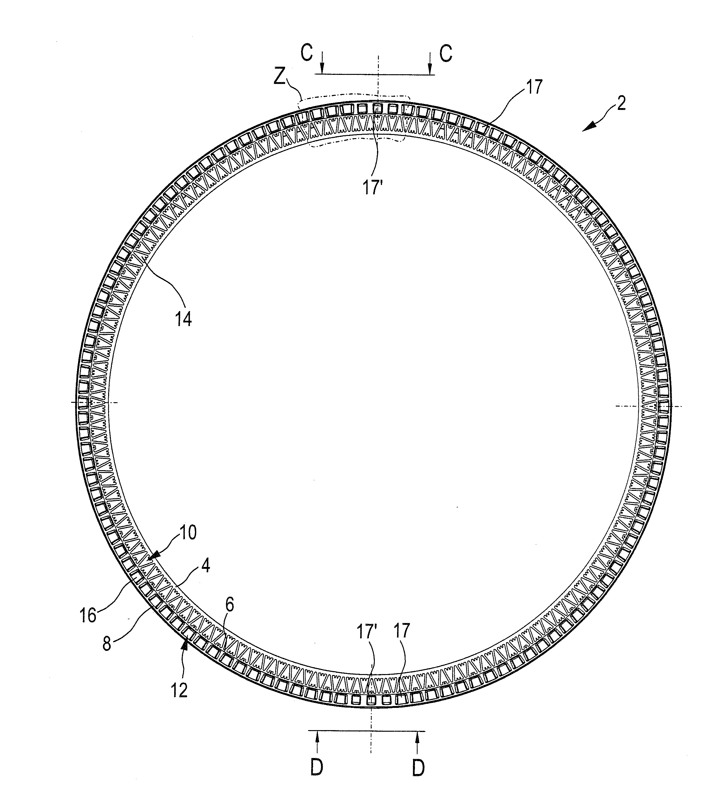
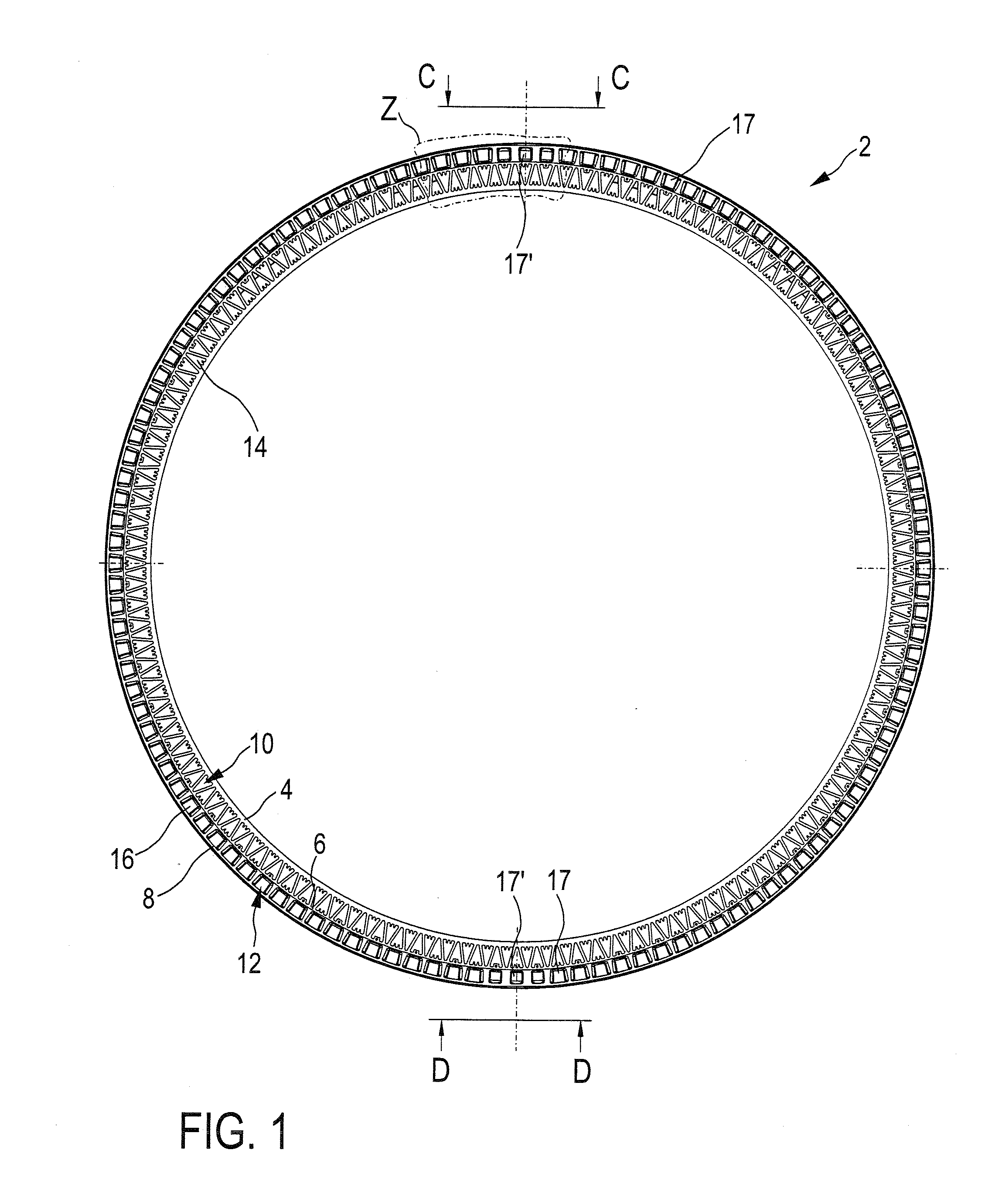
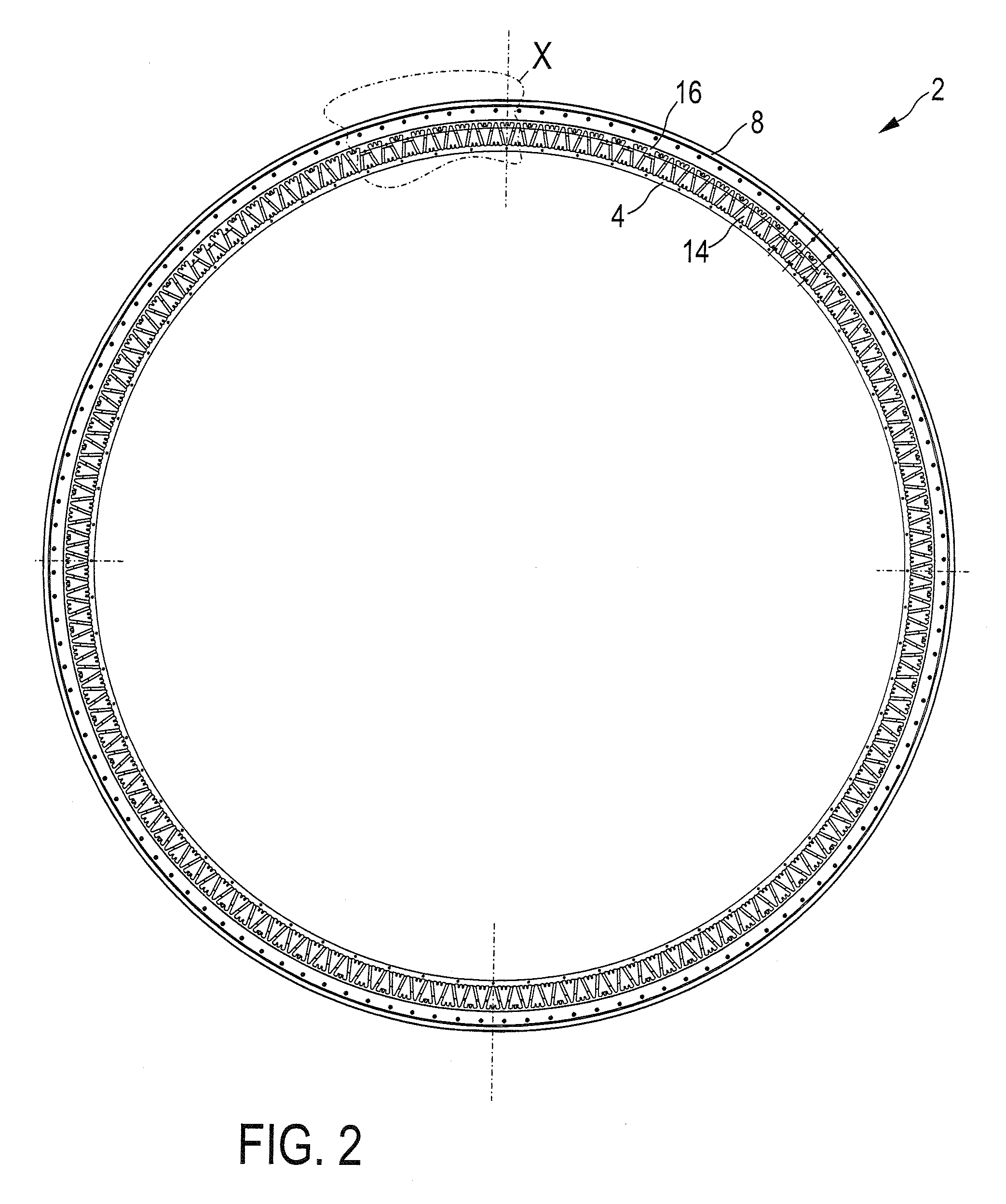
[0070]The stator ring 2 shown in FIG. 1 is of a ring-shaped configuration and forms a part of a ring generator with an internal rotor. The stator ring 2 has an inner carrier ring 4, a central carrier ring 6 and an outer carrier ring 8. Provided between the inner and outer carrier rings 4, 6 is an active cooling portion 10 while a passive cooling portion 12 is provided between the central and outer carrier rings 6, 8. As illustrated, the stator ring 2 is cast in one piece including the inner, central and outer carrier rings 4, 6, 8 and active and passive cooling portions 10, 12, the material used being aluminium.

[0071]The inner, central and outer carrier rings 4, 6, 8 provide for stability and stiffness by virtue of their substantially solid nature. To guide a magnetic field, a suitable magnetically well-conductive laminated core carrying stator windings is to...


PUM


Abstract

A ring generator of a wind power installation is provided comprising a stator having a peripherally extending stator ring for receiving stator windings and a rotor mounted rotatably about an axis of rotation relative to the stator, wherein the stator ring has cooling passages for cooling the stator by an air flow. A ring generator of a wind power installation is also provided having a stator, a peripherally extending stator ring for receiving stator windings, a rotor mounted rotatably relative to the stator and a stator bell connected to the stator ring for providing a pressure chamber with an increased or reduced pressure for providing an air flow through and/or along the stator and/or rotor for cooling the ring generator, wherein the stator bell has at least one fan opening provided with a fan.

Description

BACKGROUND[0001]1. Technical Field[0002]The present disclosure concerns a ring generator of a wind power installation. In addition the present disclosure concerns a method of controlling a wind power installation and further concerns a wind power installation.[0003]2. Description of the Related Art[0004]A wind power installation converts mechanical work taken from the wind into electric energy by means of an electric generator. In that respect a ring generator is a slowly rotating generator which manages without a transmission between the rotor of the generator and the mechanical rotor assembly which has rotor blades. For that purpose the ring generator has a multiplicity of poles. The number of poles can be of the order of magnitude of 20 up to 84 poles and even more. In that respect the ring generator is of a comparatively large diameter in comparison with its axial extent. For example the ring generator of a modern wind power installation of 7 or more megawatts nominal power is o...

Claims


Application Information

Patent Timeline
Patent Type & Authority Applications(United States)
IPC IPC(8): F03D9/00
CPCF03D9/002F04D29/582H02K5/20Y02E10/722Y02E10/721H02K7/1838H02K9/04Y02E10/725F03D9/25Y02E10/72H02K5/207H02K9/18F03D9/00F03D17/00F03D80/60
Inventor GUDEWER, WILKO
Owner WOBBEN ALOYS
Why Eureka
Try Eureka