Turbo-charged relaxation oscillator method and apparatus

a relaxation oscillator and oscillator technology, applied in the direction of pulse generators, pulse techniques, electrical apparatus, etc., can solve the problems of affecting the modulation linearity, and the oscillating signal produced by the relaxation oscillator cannot have a waveform capable of concurrently

Active Publication Date: 2006-11-21
RICHWAVE TECH CORP
View PDF7 Cites 16 Cited by
  • Summary
  • Abstract
  • Description
  • Claims
  • Application Information

AI Technical Summary

Benefits of technology

[0011]In a preferred embodiment of the present invention, the oscillating signal has a waveform with a fixed ratio of the slope of a normal discharge to the slope of an turbo-discharging, and the fixed ratio is determined by the waveform of a simulated oscillating signal during a normal charging and discharging without going through a time delay.

Problems solved by technology

However, the existence of the time delay will make the frequency of the oscillating signal not directly proportional to the current supplied by the current sources 110, 120, which will adversely affect the modulation linearity.
Therefore, the oscillating signal produced by the relaxation oscillator cannot have a waveform capable of concurrently eliminating the phase noise and jitter and solving the modulation linearity problem.

Method used


Image

  • Turbo-charged relaxation oscillator method and apparatus
  • Turbo-charged relaxation oscillator method and apparatus
  • Turbo-charged relaxation oscillator method and apparatus

Examples


Embodiment Construction

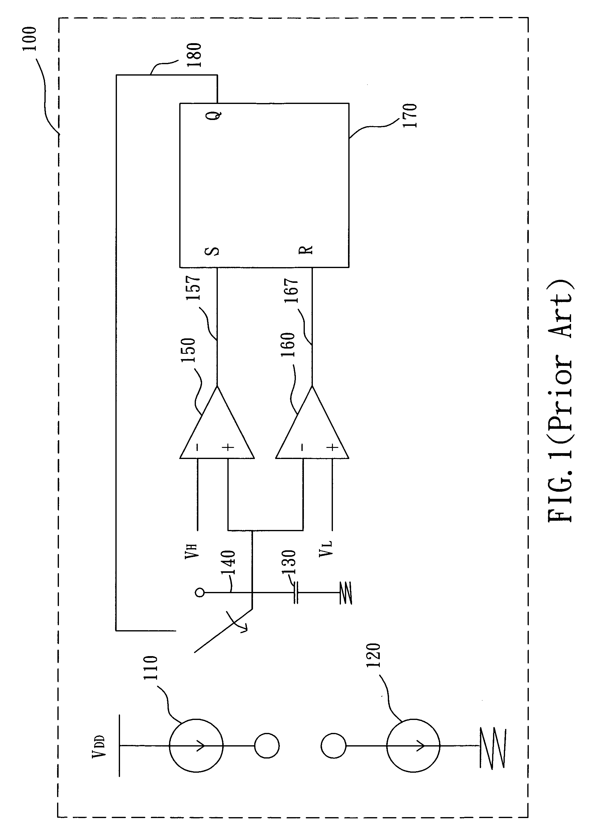
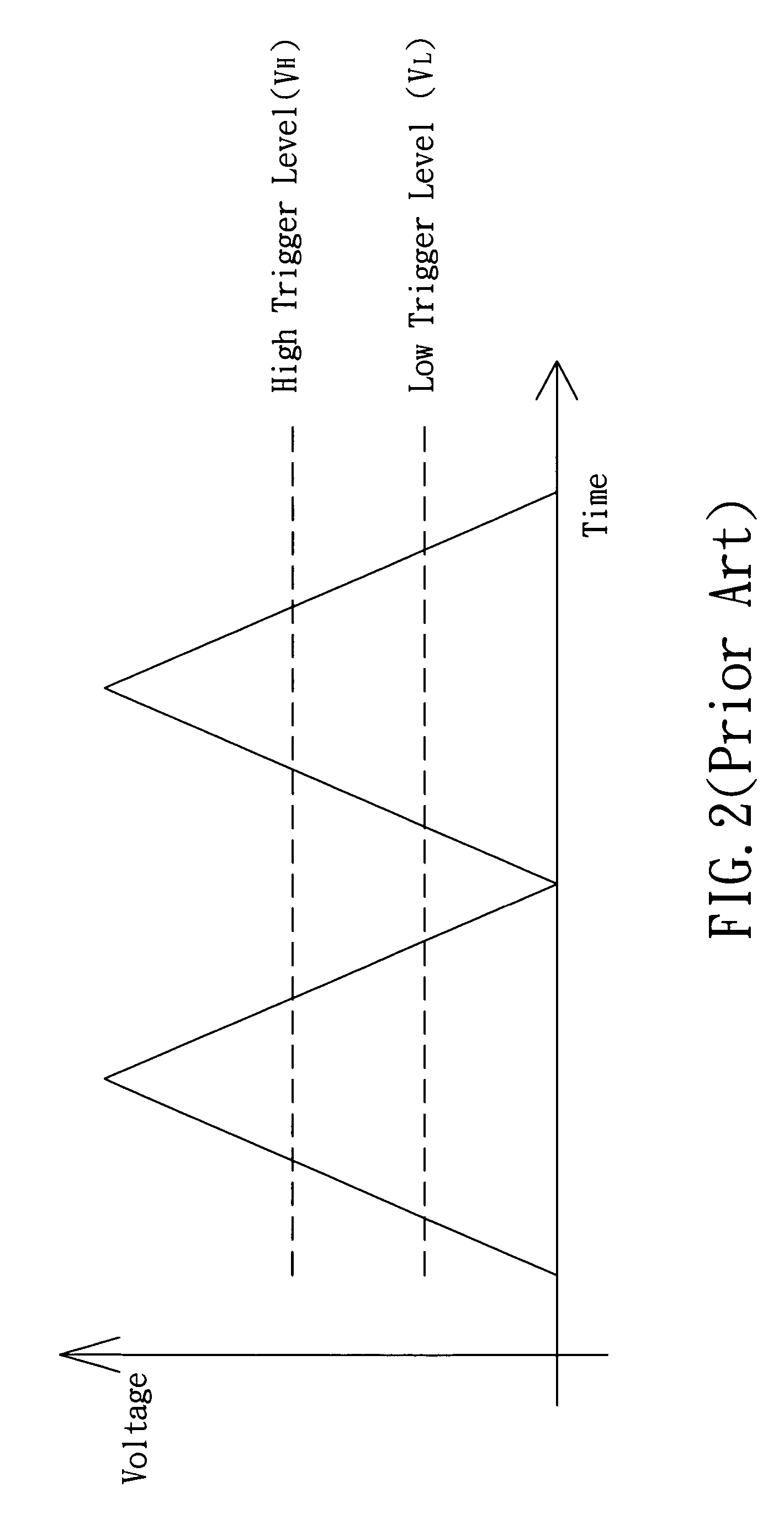
[0026]Since the components inside a prior-art relaxation oscillator has a response time, therefore the waveform of an oscillating signal produced by a prior-art relaxation oscillator will go beyond the high trigger level and the low trigger level.

[0027]If the delay time of an oscillating signal is shortened when the waveform still indicates a time delay and the simulated waveform of the oscillating signal occurs at the ideal path, then the invention will concurrently achieve the effects of eliminating the phase noise and jitter and maintaining good modulation linearity.

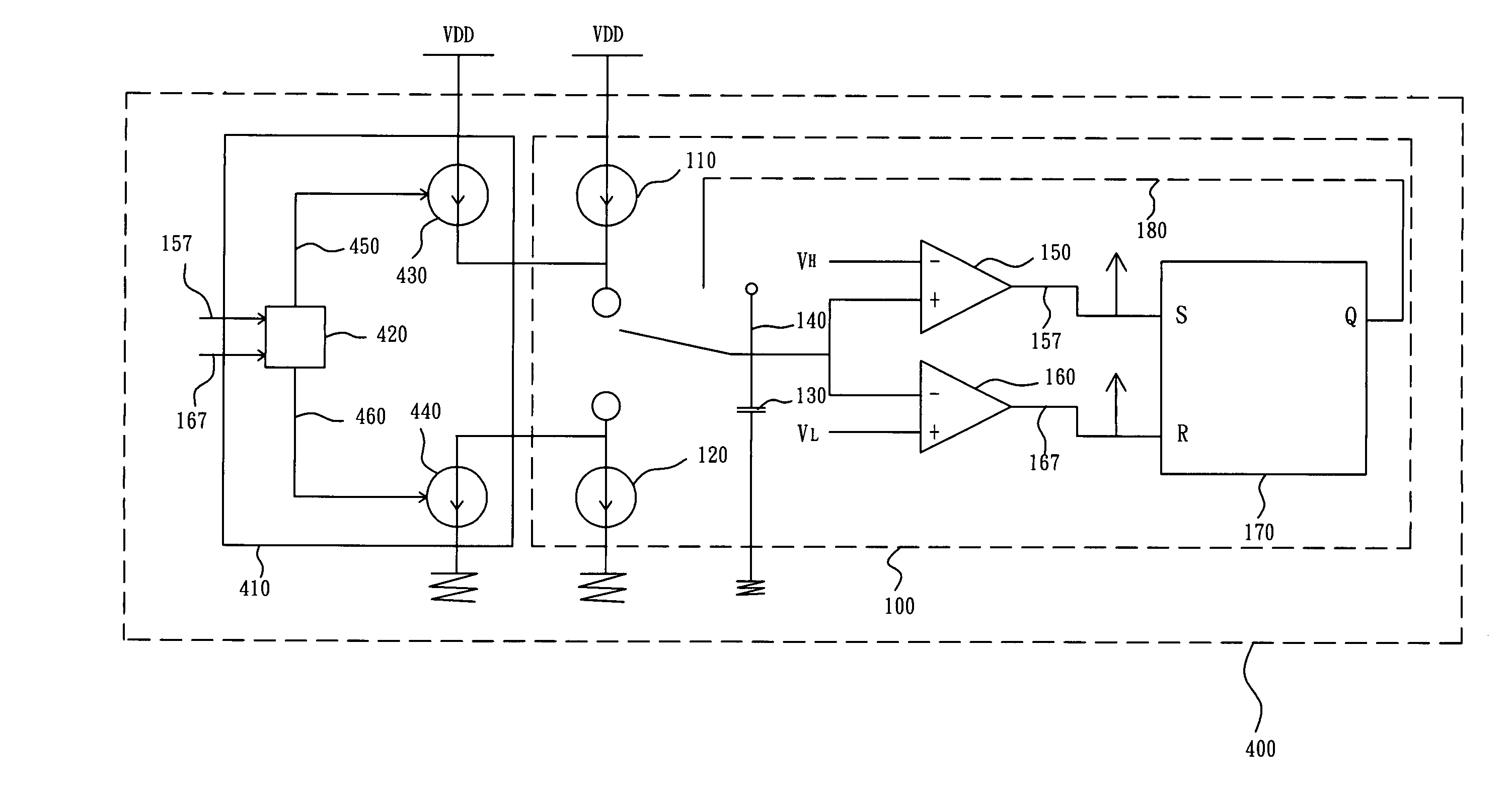
[0028]If a larger charging / discharging current is provided at an initial charge / discharge stage of a relaxation oscillator according to the present invention, which accelerates the charge / discharge, the waveform of an ideal simulated oscillating signal follows the normal charge / discharge path after passing through the high trigger level and the low trigger level. After the normal charge / discharge is resumed, some part...


PUM


Abstract

A method for producing an oscillating signal comprises: generating an oscillating signal by discharging after charging to a high trigger level and charging after discharging to a low trigger level; and turbo-charging at the initial of a change-over from charging to discharging while resuming a normal charging / discharging thereafter, and vice versa. The present invention makes use of the turbo-charging / discharging for a linear compensation, such that the produced oscillating signal has the features of concurrently eliminating phase noises and jitters as well as maintaining the modulation linearity.

Description

FIELD OF THE INVENTION[0001]The present invention relates to a method and apparatus for producing an oscillating signal, and more particularly to a method and an apparatus for producing an oscillating signal by turbo compensation.BACKGROUND OF THE INVENTION[0002]A common relaxation oscillator, such as a relaxation voltage / current controlled oscillator, is an oscillator circuit as seen in FIG. 1. In FIG. 1, the relaxation oscillator 100 mainly uses current sources 110, 120 to alternate the charge and discharge of a capacitor 130 so as to produce an oscillating signal at a node 140. That is, the voltage at the node 140 is inputted to the two comparators 150 and 160 while independent reference voltages, namely VH and VL, are coupled to each of the remaining inputs of the comparators 150, 160. The outputs of each of the two comparators 150, 160 are respectively coupled to the inputs of a “Set-Reset type” flip-flop, that is, respectively to the S terminal and R terminal of the SR latch 1...

Claims


Application Information

Patent Timeline
Patent Type & Authority Patents(United States)
IPC IPC(8): H03K3/02H03K3/26H03K3/00H03K3/012H03K3/013H03K3/0231
CPCH03K3/0231H03K3/013H03K3/012
Inventor MA, SSU-PINCHEN, SHAO-HUA
Owner RICHWAVE TECH CORP
Why Eureka
Try Eureka