
Power conversion from piezoelectric source with multi-stage storage

a piezoelectric source and power conversion technology, applied in piezoelectric/electrostriction/magnetostriction machines, tire measurements, vehicle components, etc., can solve the problems of obviating many complications regarding tire electronics solely powered by batteries, and achieve the effect of facilitating greater functionality of tire electronics and reducing the amount of required signal hardwar

Active Publication Date: 2006-11-21
MICHELIN RECH & TECH SA
View PDF38 Cites 38 Cited by
  • Summary
  • Abstract
  • Description
  • Claims
  • Application Information

AI Technical Summary

Benefits of technology

"The present patent is about a system and method for powering electronic components in a tire using piezoelectric technology. This technology is used to convert mechanical strain into electrical energy, which is then harvested, conditioned, and stored in a power storage device. The stored energy can be used to power electronic devices in the tire, such as sensors and RF transmitters. The system offers advantages over conventional battery-powered systems, as it is not dependent on battery replacement. It also allows for more functionality and higher-level equipment in the tire. The patent describes an improved tire monitoring system that measures and transmits information regarding tire conditions, as well as a method for generating and conditioning power from piezoelectric materials integrated within the tire and wheel assembly."

Problems solved by technology

Although batteries and battery-operated devices may still be incorporated with aspects of the present subject matter, many complications regarding tire electronics that are solely powered by batteries are obviated in accordance with the disclosed technology.

Method used


Image

  • Power conversion from piezoelectric source with multi-stage storage
  • Power conversion from piezoelectric source with multi-stage storage
  • Power conversion from piezoelectric source with multi-stage storage

Examples


Embodiment Construction

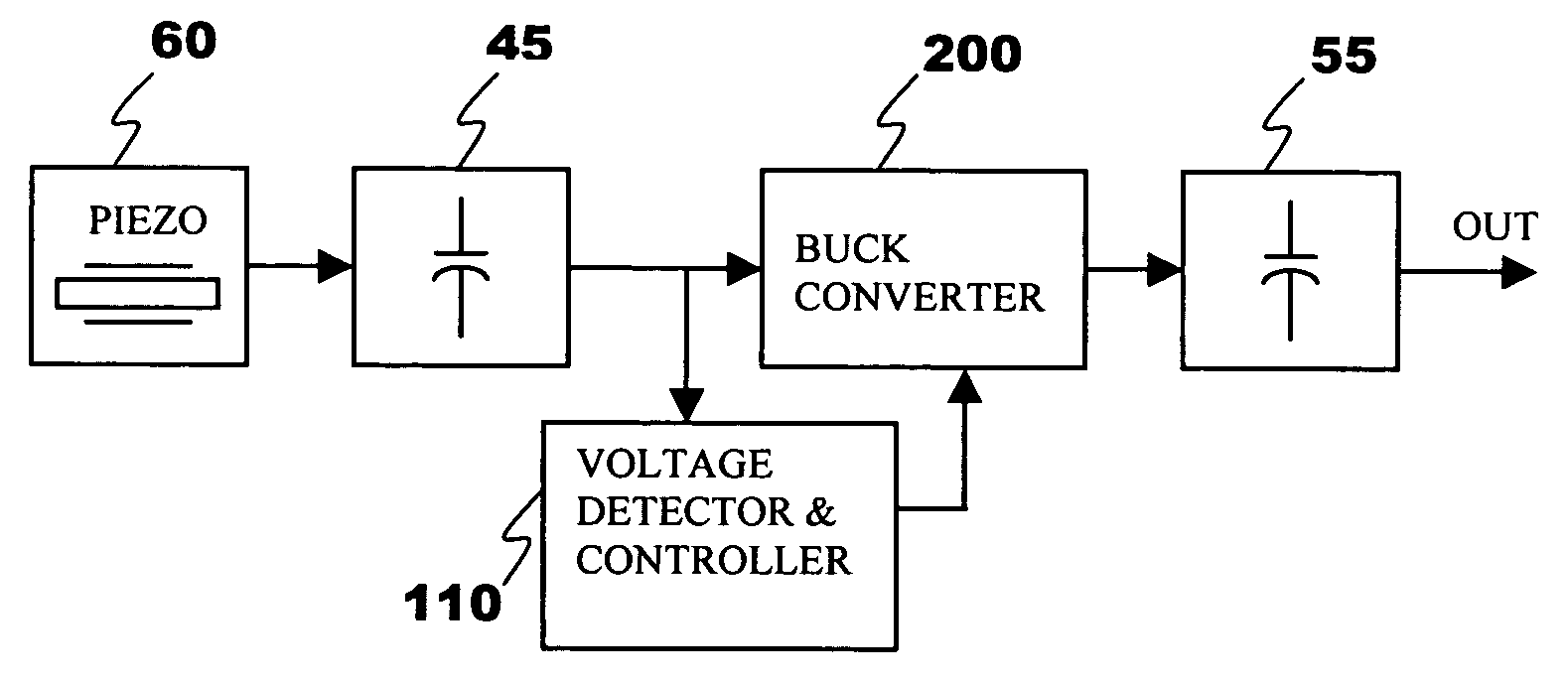
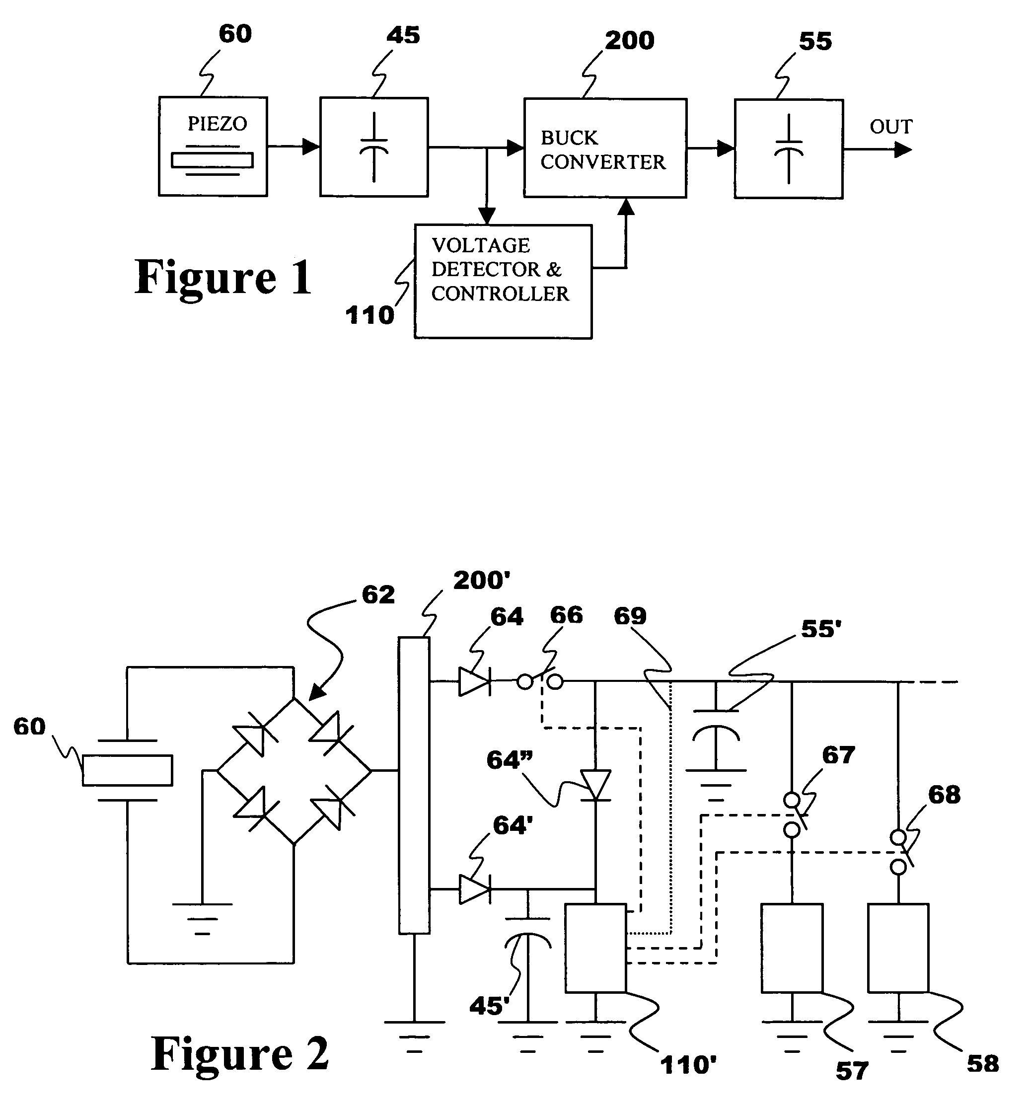
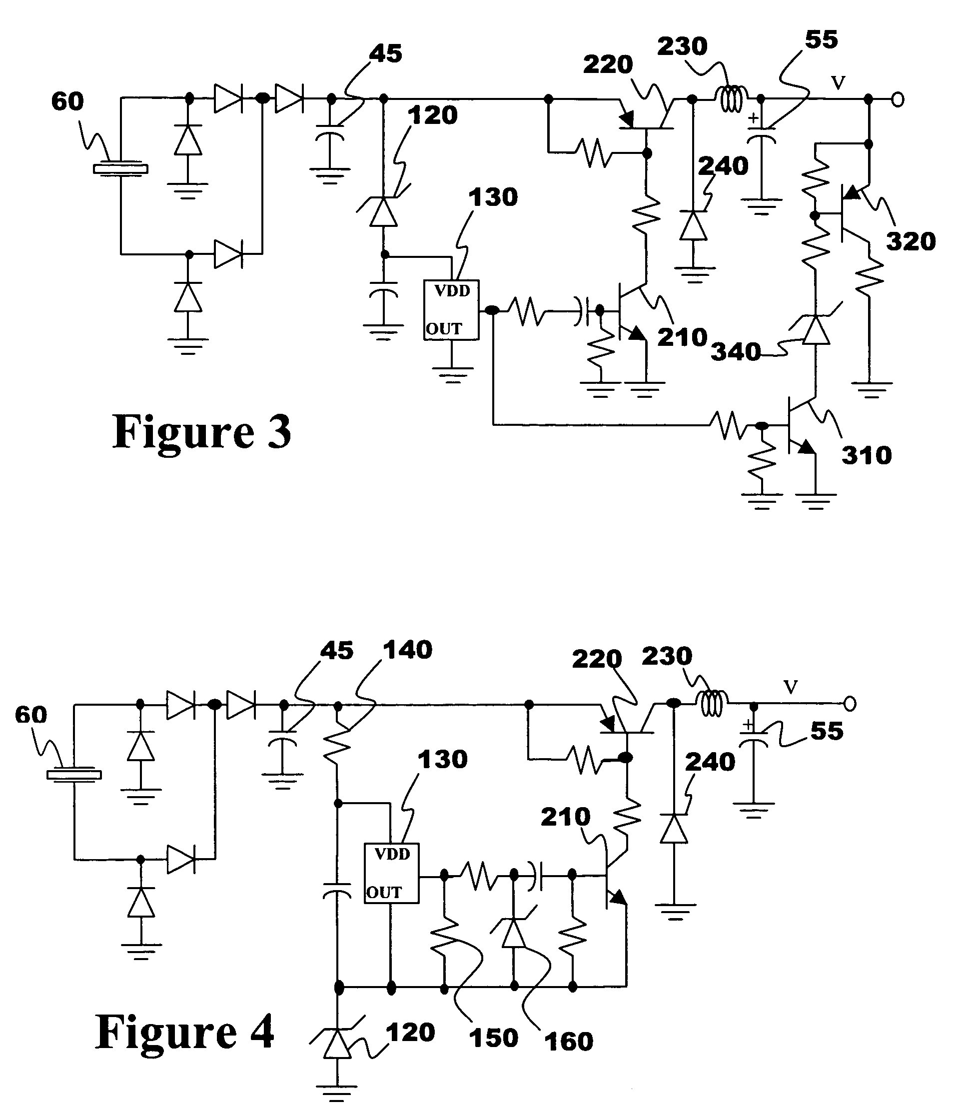
[0031]As discussed in the Brief Summary of the Invention section, the present subject matter is particularly concerned with an improved system and method for powering electronic systems mounted on or integrated within a tire structure. A power generation device utilizes piezoelectric technology to convert mechanical strain associated with tire flexure to electric current that is then conditioned and stored in one or more energy storage devices. Sufficient accumulations of such stored energy can then power electronic systems, examples of which include components for identifying various physical tire parameters as well as radio frequency (RF) transmission devices.

[0032]A power generation device in accordance with the disclosed technology generally includes two exemplary components, a piezoelectric power generating structure and a power harvesting and conditioning module. Aspects of a known exemplary piezoelectric structure are described with reference to FIG. 2 of co-pending U.S. appl...


PUM


Abstract

A system and corresponding method for generating electric power from a rotating tire's mechanical energy concerns a piezoelectric power generation device associated with a power harvesting and conditioning module. The piezoelectric structure is preferably mounted within a tire structure such that electric charge is generated therein as the wheel assembly moves along a ground surface. The electrodes of the piezoelectric structure are coupled to a power harvesting and conditioning module that rectifies the resultant electric current from the piezoelectric structure, conditions and stores it in a multi-stage energy storage device, preferably a plurality of capacitors. A regulated voltage source is provided from the energy stored in the power generation device and can be used to selectively power various electronics systems integrated within a tire or wheel assembly. An example of an integrated tire electronics system for use with the disclosed power generation device corresponds to a tire monitoring system that wirelessly transmits such information as tire pressure, temperature and identification variables to a remote receiver location.

Description

PRIORITY CLAIMField of the Invention[0001]The present invention generally concerns a system and method for converting energy generated by a piezoelectric structure exposed to the mechanical energy of conventional tire rotation, into a form suitable for providing electric power for integrated tire electronics. Piezoelectric technology is utilized to convert mechanical strain associated with tire flexure to electric charge that is then conditioned and stored in one or more energy storage devices. Sufficient accumulations of such stored energy can then power electronic systems including components for identifying various physical tire parameters as well as radio frequency (RF) transmission devices which may transmit tire identification and other data.BACKGROUND OF THE INVENTION[0002]The incorporation of electronic devices with pneumatic tire structures yields many practical advantages. Tire electronics may include sensors and other components for obtaining information regarding various...

Claims


Application Information

Patent Timeline
Patent Type & Authority Patents(United States)
IPC IPC(8): B60C23/00
CPCB60C23/0411H02N2/181
Inventor TYNDALL, PATRICK A.
Owner MICHELIN RECH & TECH SA
Learn More