Disk array device

a disk array device and array technology, applied in the direction of insulated conductors, power cables, cables, etc., can solve the problems of increasing environmental burden, increasing costs, and dummy hdds are not so convenient, so as to reduce the cooling efficiency caused by the difference of conditions between mounted and unmounted sections of storage units, reduce the effect of reducing and/or eliminating the disk array devi

Active Publication Date: 2006-11-21
GOOGLE LLC
View PDF10 Cites 95 Cited by
  • Summary
  • Abstract
  • Description
  • Claims
  • Application Information

AI Technical Summary

Benefits of technology

[0007]The present invention is made in view of the above-mentioned problems, and an object of the present invention is to provide a technique of a disk array device (disk array system), which is capable of mounting a plurality of storage units thereon and has a function of cooling the respective units in the device including the storage units by flow of cooling air by a fan operation, wherein reduction of cooling efficiency caused by a difference between conditions at a mounted section and an unmounted section of the storage unit can be prevented and using of dummy storage units (dummy HDDs) can be reduced or eliminated.
[0011]By the means for adjusting the open area rate of the vent hole, the volume of the cooling air from the storage-unit unmounted section in the housing is restricted, the pressure drop caused by inflow of the cooling wind from the storage-unit unmounted section with less flow resistance is prevented, and the volume of the cooling air in the storage-unit mounted section is secured. Consequently, even when the storage-unit mounted and unmounted conditions are mixed, the cooling efficiency to each section including the storage unit can be secured without a need of mounting dummy storage units (dummy HDDs) of the shape similarly to the storage unit in the region to which the storage units are mounted.
[0023]In addition, it may be configured to have a construction such as a shutter not in the vicinity of the backboard surface but in the vicinity of the opening surface on the side to which the storage unit of the housing is provided for the vent hole of the backboard. In the region on the side to which the storage unit of the housing is provided, a construction such as shutter is provided in the size to cover a surface for the position to insert and detach the storage unit. The relevant shutter similarly has a mechanism for opening when the storage unit is mounted and closing when it is not mounted. A portion from the housing front surface to the backboard is made into an independent airtight conduit structure in units of portions for mounting and accommodating one storage unit. For example, it is configured to have a structure which separates each storage unit in the housing. In the vent passage in the region on the side to which the storage unit of the housing is mounted, since the area of the opening surface is adjusted by opening and closing the shutter, an effect of adjusting the volume of the cooling air can be obtained in the same manner as is the case of adjusting the open area rate of the vent hole of the backboard.
[0035]According to the disk array unit according to the present invention, drop of the cooling efficiency caused by the difference of conditions between the mounted and unmounted sections of the storage unit can be prevented, and the use of dummy storage units (dummy HDDs) in the disk array device can be reduced and / or eliminated to achieve a simple cooling system. By reducing the use of dummy storage units, effects of cost reduction and environmental load can be obtained. In addition, since the storage space for dummy storage units is no longer required, ease of use is increased.
[0036]In addition, by the means of Item (1) presented as a means for particularly solving the above-mentioned problem, the air volume adjustment is made easier by the shutter, enabling efficient cooling for the storage unit.
[0037]In addition, by the means of Item (2) presented as a means for particularly solving the above-mentioned problem, efficient cooling of each portion inside the device is possible in accordance with the device condition, which is effective as an energy-saving technique, too.

Problems solved by technology

The increase of the number of dummy HDDs results in an increase of cost.
In addition, when HDDs are extended to a disk array device, dummy HDDs become wastes, causing an increase of environmental burden, too.
Furthermore, dummy HDDs are not so much convenient because dummy HDDs must be kept in stock in case of emergency or others.

Method used


Image

  • Disk array device
  • Disk array device
  • Disk array device

Examples


first embodiment

[0070

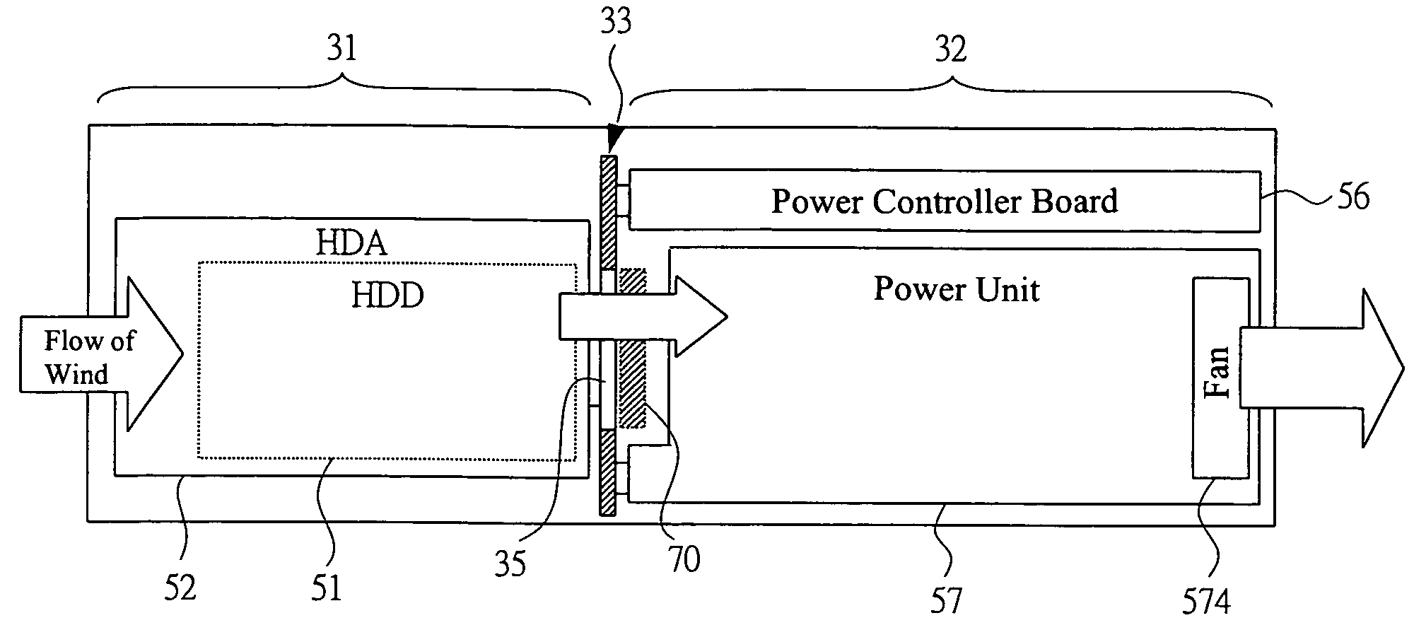
[0071]A disk array system (disk array device) according to a first embodiment of the present invention controls, as a means for cooling the interior of the system, an open area rate of a vent hole by: providing a shutter corresponding to the vent hole of a backboard in a chassis (housing); and opening / closing the shutter by insertion and removal of a storage unit (HDA) into and from the chassis. By this, a volume of cooling air flowing in a vent passage in a HDA unmounted section having low flow resistance is restricted to secure the volume of the cooling air at a HDA mounted section, and controls the volume of the cooling air flowing in the whole chassis including the vent passage of the HDA unmounted section and the vent passage of the HDA mounted section.

[0072]

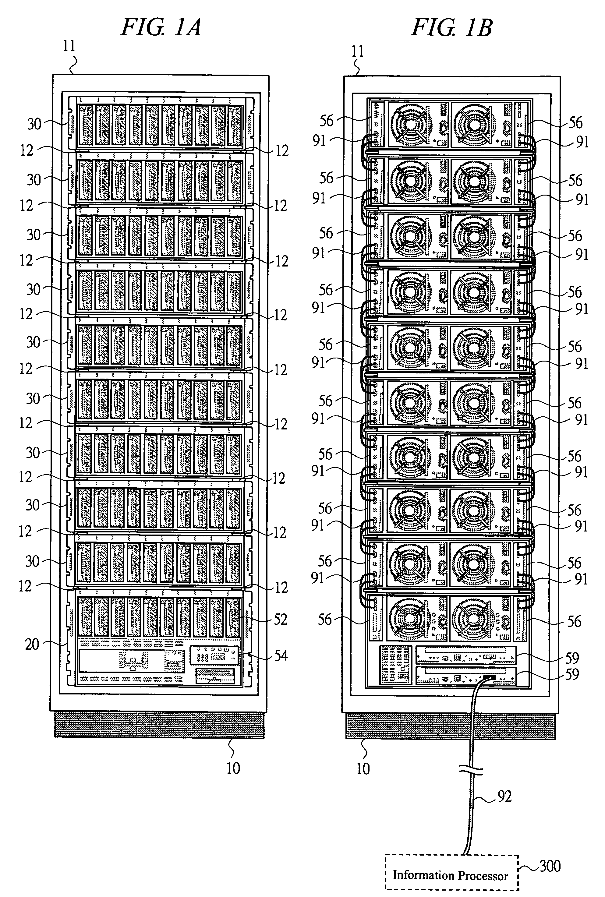
[0073]FIGS. 1A and 1B show a hardware appearance configuration of a disk array system 10 according to an embodiment of the present invention. The configuration of the disk array system 10 is common to respective embodi...

second embodiment

[0142

[0143]FIG. 14 is an explanatory view for showing a construction related to the shutter 70b in a disk array system (disk array system) of a second embodiment. It schematically shows a vent hole 35 and a shutter 70b as viewed from the front of the backboard 33. In the first embodiment, a shape of the door portion of the shutter 70 has been designed to be a rectangle so that it matches the shape of the vent hole 35. However, as shown in the shutter 70b (shaded portion) of this Figure, it is possible to design it into a specified shape without being limited to a rectangle etc. By way of an example, the shape of the door portion of the shutter 70b is designed in such a manner that the vent hole 35 at the center has a larger opening than that at its edge in the closed condition of the shutter 70b. The relevant shape is a design example which meets the case in which a heat generating section is located at the position (shown by the dotted frame) near the center of the vent hole 35 in ...

third embodiment

[0144

[0145]FIG. 15 is an explanatory view for showing a construction related to a shutter 70c in a disk array system (disk array device) of a third embodiment. It shows a sectional view taken in a horizontal direction of the housing in the mounted / unmounted conditions of the HDA onto the backboard. The mechanism for opening and closing the shutter 70 may not be limited to the press-opening mechanism by the pin 71 installed to the HDA 52 as described in the first embodiment. In the third embodiment, as shown in this Figure, a lever 73 which is a mechanism for operating by the door portion of the shutter 70c is installed on the front side (HDA mounted side) of the backboard 33. The lever 73 is located at such a position that a force is applied due to physical contact with the back surface of the HDA 52 by the insertion and contact of the HDA 52 and the lever is pressed down. It is a mechanical construction for opening the door portion of the shutter 70c by the relevant lever 73 as the...


PUM


Abstract

In a disk array device for cooling respective sections including a HDD by a fan, drop of cooling efficiency by the difference of conditions of HDD mounted and unmounted sections is prevented and the use of a dummy HDD is deleted / eliminated. A housing contains a HDA mounted on the HDD, a power controller board for performing control to the HDD, a power unit for supplying power to each section, a fan for cooling the housing therein, and a backboard for connecting all the sections. On one backboard surface, the HDA is mounted, which has a cooling function for making cooling air flowing in the housing and exhausting air from the housing via a region on which the HDA are mounted and via a vent hole on the backboard. For the vent hole, a shutter is mounted, which has a mechanism for adjusting an open area rate of the vent hole by opening when the HDA is mounted and closing when removed.

Description

CROSS-REFERENCE TO RELATED APPLICATION[0001]The present application claims priority from Japanese patent application No. JP 2004-240342 filed on Aug. 20, 2004, the content of which is hereby incorporated by reference into this application.BACKGROUND OF THE INVENTION[0002]The present invention relates to a disk array device (also called a storage system), and in particular, to a technique for cooling HDD (hard disk drive) and others to be installed in a housing.[0003]As processing in a disk array device increases, it is essential to efficiently carry out cooling against the heat generated from each section inside the device including HDD. For the cooling means, a fan is installed in the disk array device, and the wind for air cooling (cooling air) is circulated to each component including HDDs inside the equipment by the fan operation.[0004]In addition, in a disk array device in which a plurality of HDDs can be mounted, there occur an HDD mounted section (hereinafter, “HDD mounted se...

Claims


Application Information

Patent Timeline
Patent Type & Authority Patents(United States)
IPC IPC(8): H05K7/20
CPCG06F1/20G11B33/126G11B33/128
Inventor CHIKUSA, TAKASHIHORI, MASANORITACHIBANA, TOSHIOMAKI, TAKEHIROHONMA, HIROTAKA
Owner GOOGLE LLC
Why Eureka
Try Eureka