Multi-frequency data transmission channel power allocation

a multi-frequency data and power allocation technology, applied in the field of digital communications, can solve problems such as significant increases in data rate, and achieve the effects of increasing data rate, reducing data rate, and transferring additional bits more efficiently

Inactive Publication Date: 2006-11-21
AMERICAN TELEPHONE & TELEGRAPH CO
View PDF5 Cites 20 Cited by
  • Summary
  • Abstract
  • Description
  • Claims
  • Application Information

AI Technical Summary

Benefits of technology

[0013]The present invention addresses the above needs, as well as others, by providing a method and apparatus for controlling a communication device that performs additional optimization by iteratively removing power from some channels and reallocating power to other channels that can transmit additional bits more efficiently. In general, power is removed from channels in which large amounts of power may be removed without large reduction in data rate, and reallocated to channels in which relatively small amounts of power can result in significant increases in data rate. Thus, power is reallocated to channels that can transmit more efficiently. Alternatively, or in addition, the method and apparatus for controlling a communication device adjusts the operational parameters of both an outer coder and an inner coder to achieve more efficient transmission of data. In either case, the increased transmission efficiency provides the advantage of increasing the overall, multi-channel data rate for a given amount of power, or reduce the power required to transmit at a given overall data rate.

Problems solved by technology

In general, power is removed from channels in which large amounts of power may be removed without large reduction in data rate, and reallocated to channels in which relatively small amounts of power can result in significant increases in data rate.

Method used


Image

  • Multi-frequency data transmission channel power allocation
  • Multi-frequency data transmission channel power allocation
  • Multi-frequency data transmission channel power allocation

Examples


Embodiment Construction

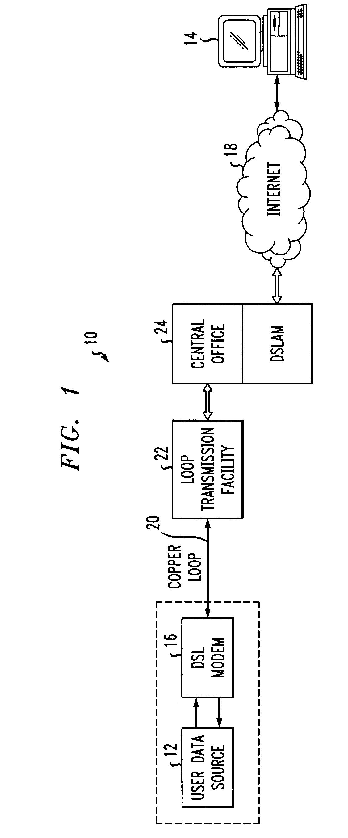
[0025]FIG. 1 shows an exemplary communication network connection 10 in which a modem according to the present invention is employed. In general, the network connection 10 facilitates the flow of data between a user data source 12 and a remote processing device 14. The user data source 12 may suitably comprise a general purpose computer such as a personal computer or the like. The remote processing device 14 may suitably be a web server device, another end-user personal computer, or other internet-capable processing device. By way of example, the user data source 12 may be an ordinary consumer and the remote processing device 14 may be a computer that hosts a commercial website that allows a user located at the user data source 12 to purchase goods or services.

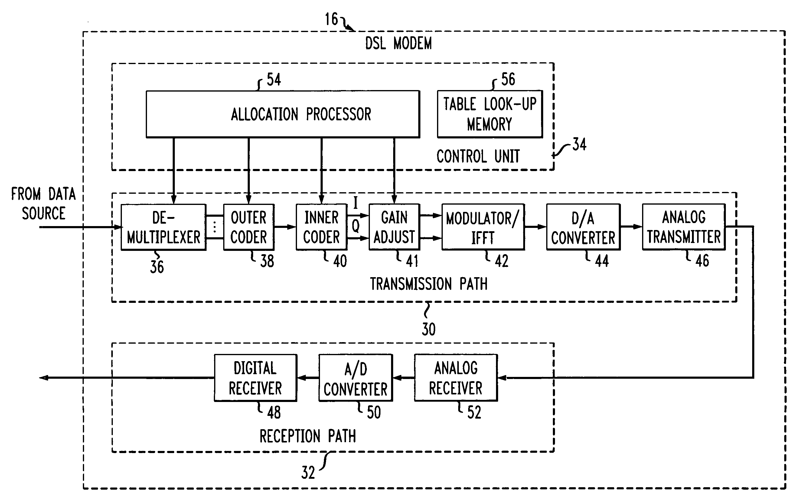
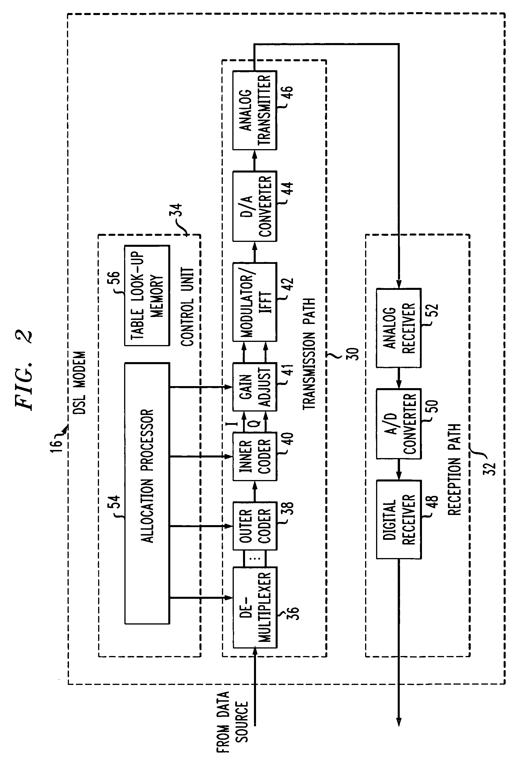
[0026]The user data source 12 is coupled to communicate data bidirectionally with a DSL modem 16. The DSL modem 16 is a device that is operable to communicate data over analog telephone lines using DMT communication techniques....


PUM


Abstract

A method of controlling a communication device that is operable to transmit digital data over a plurality of frequency channels. The method includes selecting an initial transmission power and a corresponding data rate for each channel. The method also includes identifying in a first channel a first ratio of a first decrement in transmission power to a first data rate decrement that is greater than a second ratio of a second decrement in transmission power to a second data rate decrement. Then, the initial transmission power allocation of the first channel is reduced by the first decrement. The method also includes reallocating the decremented initial transmission power of the first channel to one or more other channels.

Description

[0001]This application claims the benefit of U.S. Provisional Patent Application Ser. No. 60 / 315,724, filed Aug. 29, 2001.FIELD OF THE INVENTION[0002]The present invention relates generally to digital communications, and more particularly, to multi-frequency data transmission.BACKGROUND OF THE INVENTION[0003]Digital communications may be carried out in a variety of ways. One method involves multiple frequency data transmission over analog communication lines. For example, discrete multi-tone (DMT) communications are employed by digital communication devices to transmit data over copper twisted-pair lines. Copper twisted-pair lines have been, and continue to be, widely employed in the telephone network, particularly for residential subscriber lines. As the need for high speed data communications to residential subscribers has increased, the implementation of DMT communications via digital subscriber line (DSL) modems has increased.[0004]In the use of DMT communications, a DMT modulat...

Claims


Application Information

Patent Timeline
Patent Type & Authority Patents(United States)
IPC IPC(8): H04K1/10G06F11/00H03D1/00H04B7/00H04L1/00H04L27/26
CPCH04L1/0003H04L1/0009H04L1/0016H04L1/0065H04L5/0046H04L5/006H04L27/2608H04L5/0007Y02B60/31Y02D30/50
Inventor ERVING, RICHARD HENRYSANKARANARAYANAN, LALITHA
Owner AMERICAN TELEPHONE & TELEGRAPH CO
Why Eureka
Try Eureka