
Dead timestamp identification and elimination

a technology of time stamps and identification marks, applied in the field of dead time stamp identification and elimination, can solve the problems of increasing the sophistication of computations performed on data, taking more time to be performed, and data sets becoming temporally sparser and sparser

Inactive Publication Date: 2006-11-21
HEWLETT PACKARD DEV CO LP
View PDF2 Cites 17 Cited by
  • Summary
  • Abstract
  • Description
  • Claims
  • Application Information

AI Technical Summary

Benefits of technology

This approach improves application performance by efficiently eliminating unwanted data items, optimizing memory usage, and ensuring timely data processing, thereby enhancing system throughput and reducing computational inefficiencies.

Problems solved by technology

Computations performed on the data increase in sophistication and take more time to be performed as the data moves through the pipeline.
As a result, the data sets become temporally sparser and sparser at higher levels of processing because they correspond to higher and higher-level hypotheses of interesting events.
Indiscriminate production of unwanted items by upstream modules results in clogging the memory system because memory resources are limited.
Also, data performance guarantees such as adequate interactive response may not be met because computational resources are also limited.
Tasks may operate at different speeds, resulting in slower upstream nodes computing data that will not be used by downstream nodes.

Method used


Image

  • Dead timestamp identification and elimination
  • Dead timestamp identification and elimination
  • Dead timestamp identification and elimination

Examples


Embodiment Construction

[0022]A description of preferred embodiments of the invention follows:

[0023]FIG. 3 is a block diagram of a computer system 300 for executing an application 318 which collects garbage and eliminates unnecessary computations according to the principles of the present invention. Included in the computer system 300 are at least one Central Processing Unit (“CPU”) module 308, a memory system 306 and a system bus interface 310 connected by a processor bus 312. The CPU module 308 includes a processor (not shown). The system bus interface 310 is further connected to an Input / Output (“I / O”) system 304 by a system bus 314. An external storage device 316 is connected to the I / O system 304. The application 318 which collects garbage and eliminates unnecessary computations according to the principles of the present invention is stored in the storage device 316 and also stored in the memory system 306. The application 318 is a constrained dynamic application. For example, the constrained dynamic ...


PUM


Abstract

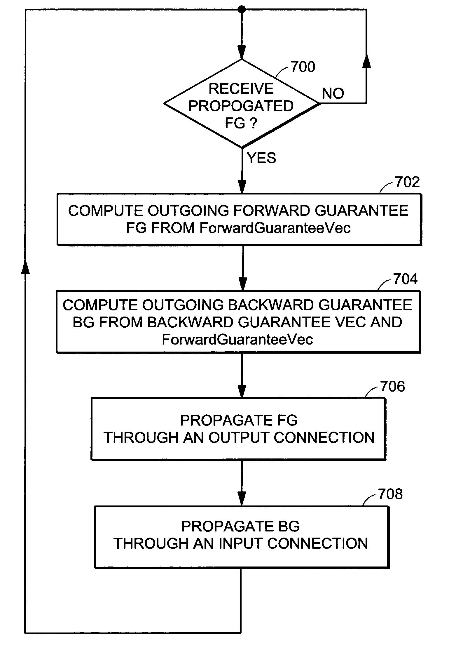
The performance of an application is improved by identifying and eliminating items with dead time-stamps and eliminating work on items with irrelevant time-stamps. An algorithm executing in each node of a task graph computes and propagates guarantees which are used to eliminate both items with dead time-stamps and irrelevant computation on dead time-stamps. A continuous garbage collector eliminates items with dead time-stamps while the node continues to process received items. Unnecessary computations are reduced by automatically discerning the interest set of downstream modules for time-stamps and feeding the interest set back to upstream modules.

Description

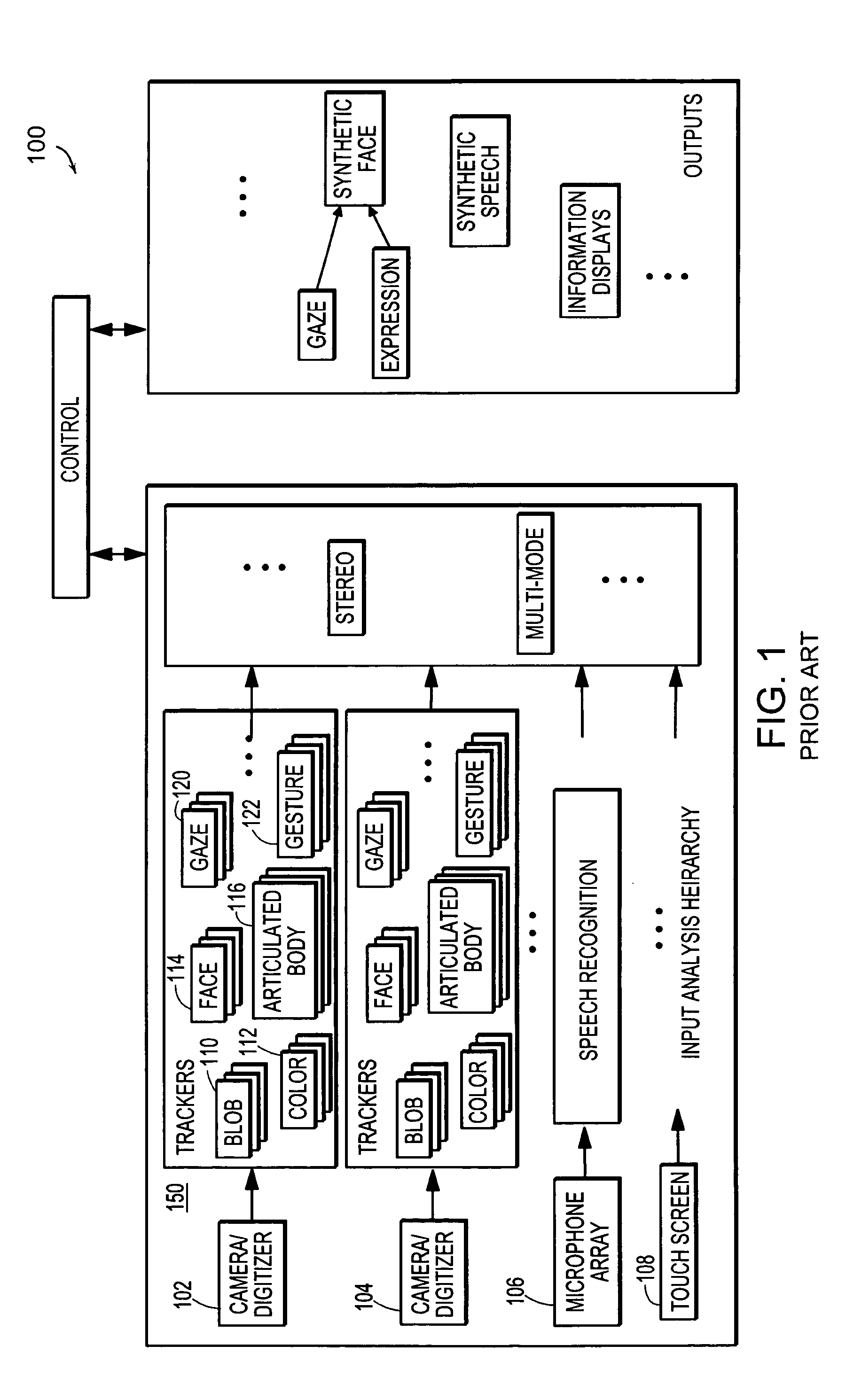
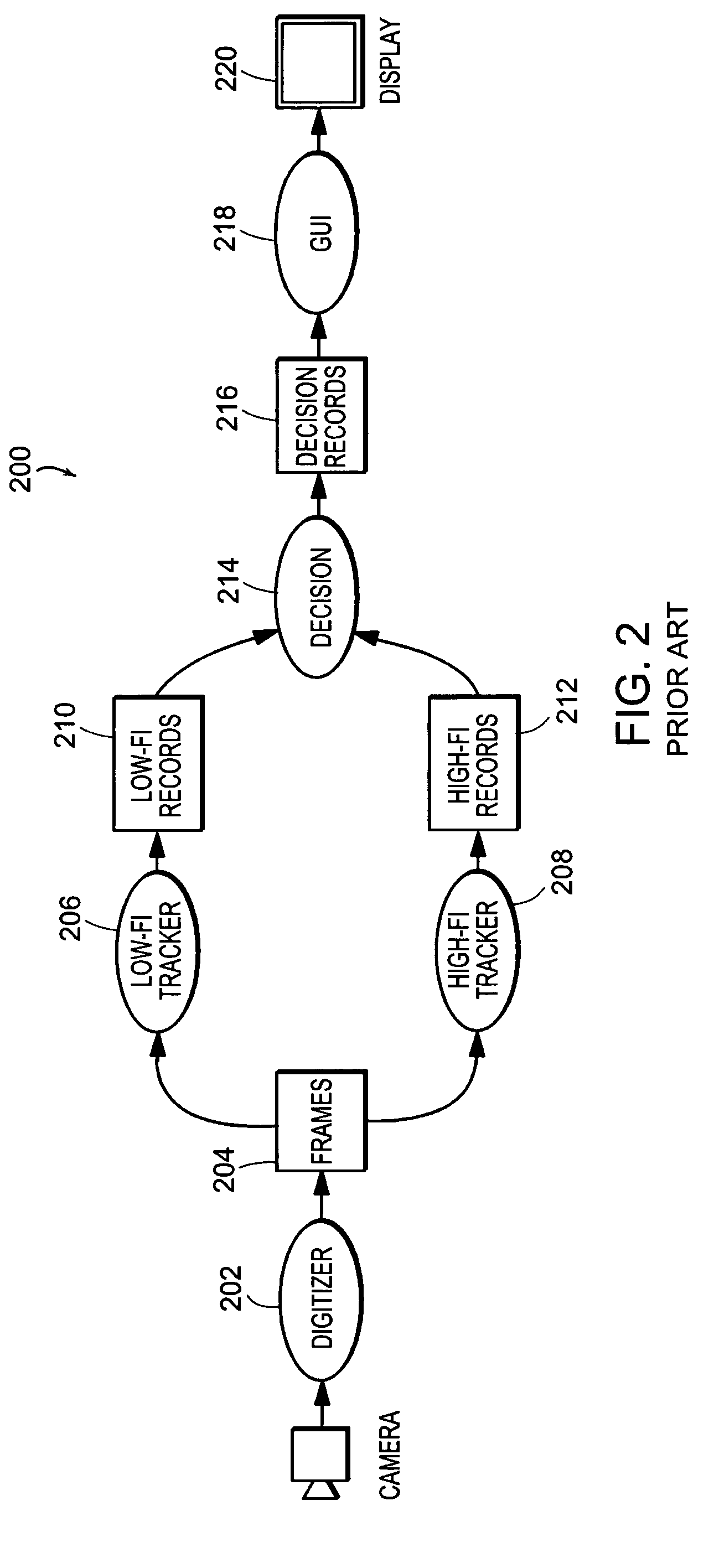
BACKGROUND OF THE INVENTION[0001]Several emerging applications are continuous in nature and the processing usually involves combining time-stamped inputs from sensors that are distributed in space with contextual data of the specific application environment. In a continuous application, upstream computational modules continuously generate data with a certain periodicity and pass the data to downstream modules for analysis and action.[0002]FIG. 1 illustrates the software architecture of a prior art continuous application for processing timestamped inputs. An example of a continuous application is a Smart Kiosk, an interactive multimedia public user interface. The Smart Kiosk 100 interacts with customers in a natural, intuitive fashion using a variety of input and output devices such as, video cameras 102, 104, microphones 106, loudspeakers, touch screens 108, infrared and ultrasonic sensors.[0003]The Smart Kiosk uses computer vision techniques to track, identify and recognize one or ...

Claims


Application Information

Patent Timeline
Patent Type & Authority Patents(United States)
IPC IPC(8): G06F17/30G06F12/00G06F12/02
CPCG06F12/0269Y10S707/99957
Inventor KNOBE, KATHLEENRAMACHANDRAN, UMAKISHORE
Owner HEWLETT PACKARD DEV CO LP
Learn More