Hydroform die tube holding assembly and method of making same

a technology of holding assembly and die tube, applied in the field of hydroforming, can solve the problems of inefficiency of sealing, inability of pneumatic clamp device to hold bent tubes in proper positions, etc., and achieve the effects of reducing downtime and die maintenance, improving sealing condition, and adding design flexibility

Inactive Publication Date: 2006-11-28
GM GLOBAL TECH OPERATIONS LLC
View PDF6 Cites 2 Cited by
  • Summary
  • Abstract
  • Description
  • Claims
  • Application Information

AI Technical Summary

Benefits of technology

[0008]One advantage of the present invention is that a hydroform die tube holding assembly is provided for hydroforming a tubular member. Another advantage of the present invention is that a method of making a hydroform die tube holding assembly is provided to form a hydroformed tubular member by holding the tubular member in position before the die closes to the bottom. Yet another advantage of the present invention is that the assembly and method adds the ability to manufacture products with additional form (sections) at the tube ends, near the seal units. Still another advantage of the present invention is that the assembly and method adds the ability to hold the round tube into position and improve sealing condition by not allowing the tube to move over the o-ring seal. A further advantage of the present invention is that the assembly and method reduces downtime and die maintenance. Yet a further advantage of the present invention is that the assembly and method adds design flexibility to locally and internally reinforce hydroformed tubular members for crashworthiness, strength, and / or stiffness improvements.

Problems solved by technology

However, vehicle strength, stiffness, and / or impactworthiness often necessitate the need for local areas of structural reinforcement to meet their design goals.
When the seal units do not directly oppose one another, the pneumatic clamp devices do not provide capability to hold the bent tube into proper position.
When finish part geometry changes round tube near seals, the tubes tend to move within the sealing process (creating sealing inefficiencies).

Method used


Image

  • Hydroform die tube holding assembly and method of making same
  • Hydroform die tube holding assembly and method of making same
  • Hydroform die tube holding assembly and method of making same

Examples


Embodiment Construction

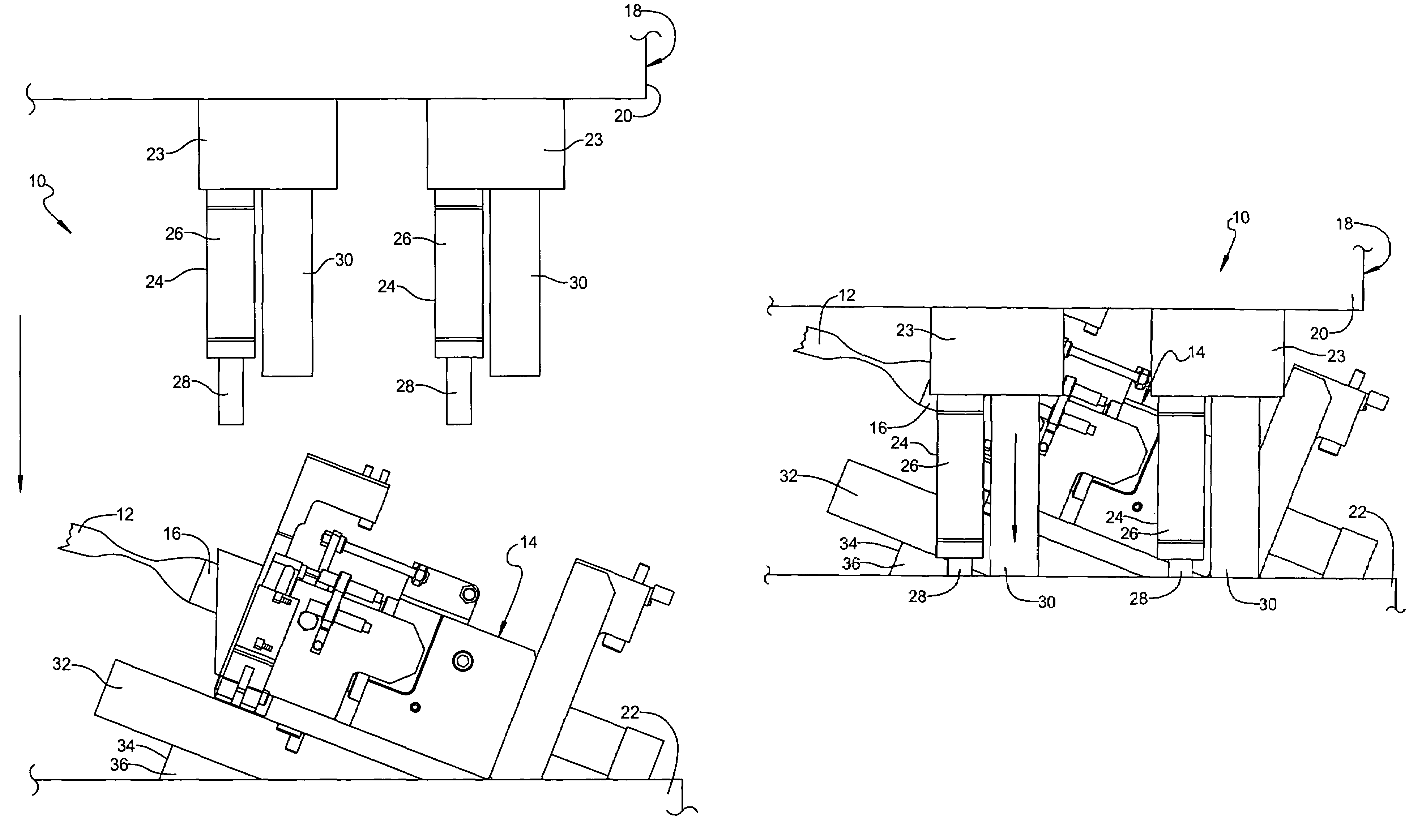
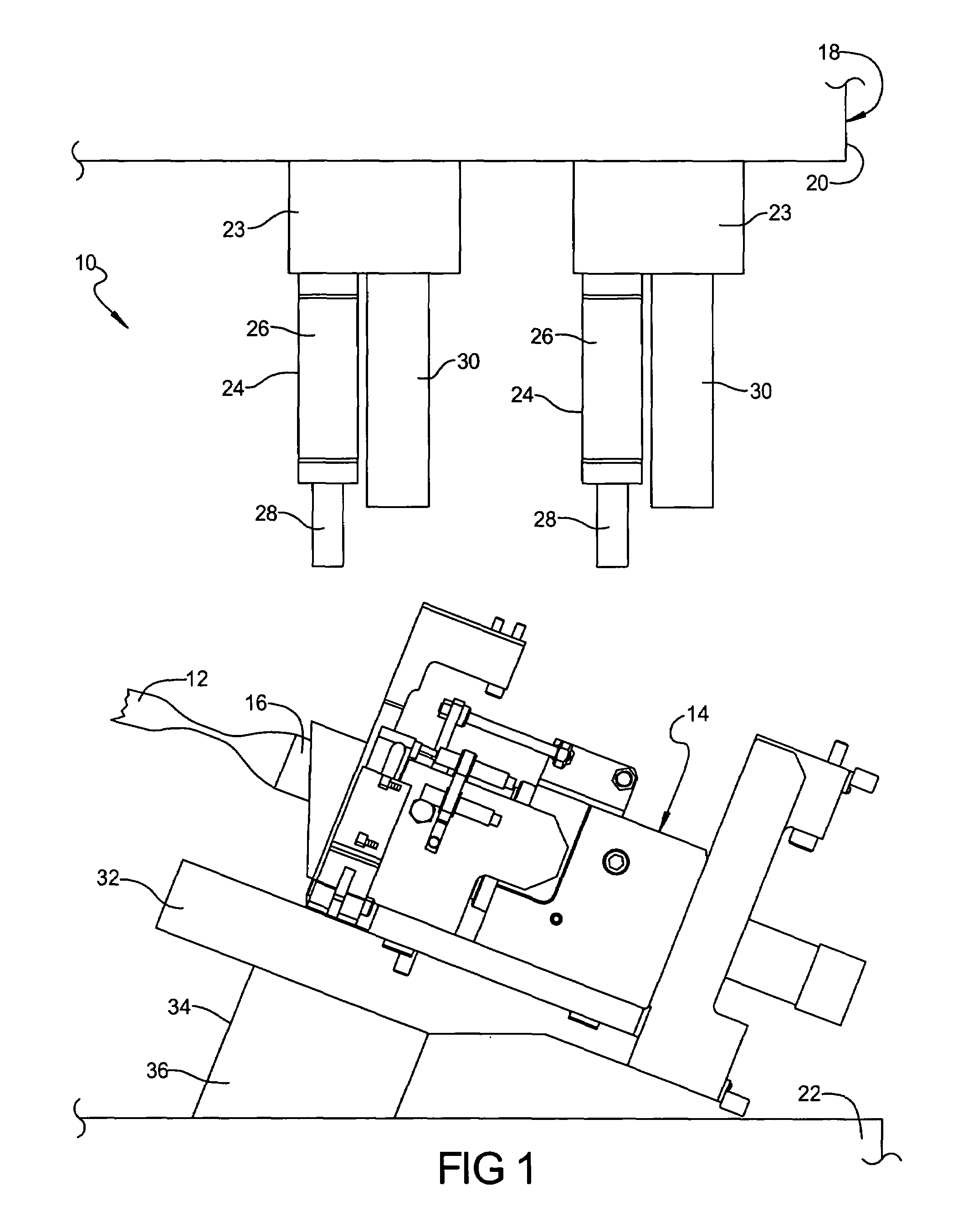
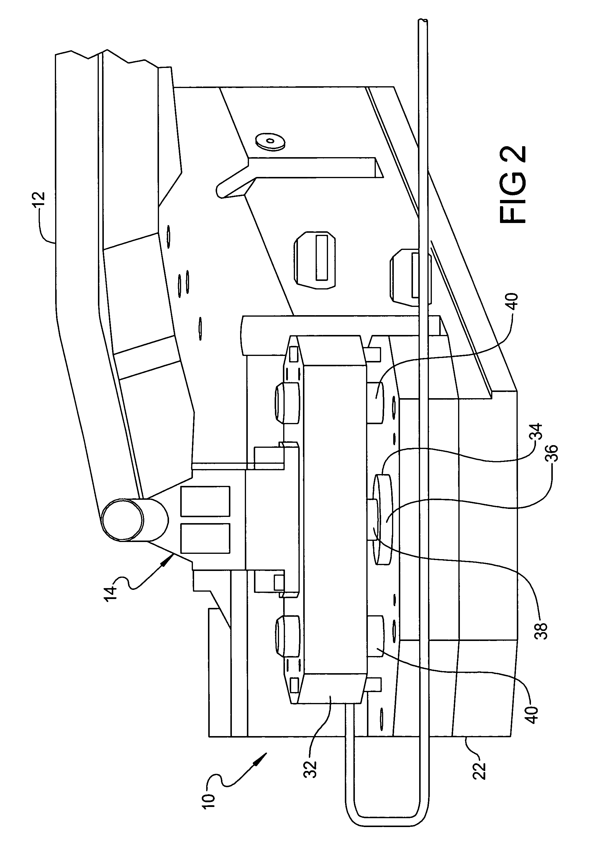
[0015]Referring to the drawings and in particular FIGS. 1 and 2, one embodiment of a hydroform die tube holding assembly 10, according to the present invention, is shown for hydroforming a tube 12 used for assembly in automotive structures (not shown) of a vehicle (not shown). The hydroform die tube holding assembly 10 includes at least one, preferably a pair of seal units, generally indicated at 14, to seal the ends of the tube 12. Each seal unit 14 includes an axial protrusion 16. One end of the tube 12 is placed over the protrusion 16 of the seal unit 14. It should be appreciated that the other end of the tube 12 would also be placed over the protrusion 16 of the other seal unit 14. It should also be appreciated that the seal units 14 do not oppose one another. It should further be appreciated that only the one seal unit 14 for the hydroform die tube holding assembly 10 will be subsequently described. It should still further be appreciated that the seal unit 14 is conventional an...


PUM

PropertyMeasurementUnit
pressureaaaaaaaaaa
cylindrical shapeaaaaaaaaaa
strengthaaaaaaaaaa

Abstract

A hydroform die tube holding assembly and method of using same includes at least one seal unit for sealing an end of a tube. The hydroformed die tube holding assembly also includes a seal unit elevator for attachment to a lower die half to operatively support the at least one seal unit. The hydroformed die tube holding assembly further includes at least one upper gas spring for attachment to an upper die half to engage, the seal unit elevator to drive the seal unit elevator downward prior to the upper die half engaging the tube.

Description

TECHNICAL FIELD[0001]The present invention relates generally to hydroforming and, more particularly, to a hydroform die tube holding assembly and method of making same for automotive structures.BACKGROUND OF THE INVENTION[0002]It is known to hydroform tubular components or members. Hydroformed tubular members are becoming increasingly popular in automotive body structural applications. During vehicle body manufacturing, many of the hydroformed tubular members are used in vehicle body and chassis applications. However, vehicle strength, stiffness, and / or impactworthiness often necessitate the need for local areas of structural reinforcement to meet their design goals.[0003]Tube sealing is a major factor in the tube hydroform process. Seal units may be mounted on nitrogen powered elevators. The tube is filled (fill pressure) and the round tube is stuffed into the die cavity to bottom. Press tonnage is applied and form pressure is initiated forming the tube to the cavity. This process ...

Claims


Application Information

Patent Timeline
Patent Type & Authority Patents(United States)
IPC IPC(8): B21D26/02B21D9/15B23P17/02
CPCB21D26/039B21D26/047B21D26/045Y10T29/49805
Inventor MARKS, KEVIN R.RABY, MICHAEL L.
Owner GM GLOBAL TECH OPERATIONS LLC
Why Eureka
Try Eureka