Socket with dual-functional composite gasket

a composite gasket and socket technology, applied in the direction of hose connection, cable termination, mechanical equipment, etc., can solve the problems of gasket leakage, entire pipe section leakage, and exclusive elastomeric material gaskets formed such as natural rubber

Inactive Publication Date: 2006-11-28
TIGRE USA
View PDF57 Cites 70 Cited by
  • Summary
  • Abstract
  • Description
  • Claims
  • Application Information

AI Technical Summary

Benefits of technology

[0007]It has now been discovered that the disadvantages associated with the use of conventional elastomeric gaskets used in combination with a retaining ring can be eliminated by the present invention. Surprisingly, it has been found that the gap between the inner wall of a bent retainer and the adjacent wall of the gasket in the resulting groove that existed in prior configurations can be eliminated by the present invention comprising a gasketed bell in the cylindrical body of a pipe or fitting, the pipe or fitting having a longitudinal axis and comprising an enlarged, generally cylindrical, one piece hub formed in the forward end of the body, with the hub having a cylindrical section of a first diameter suitable to overfit an end of an adjacent length of pipe, the hub including an integral, radially inwardly open internal groove of a second diameter, the second diameter being greater than said first diameter. The internal groove is defined forwardly by an integral, radially inwardly bent retainer and rearwardly by an integral, circular, generally angular corner with a, generally cylindrical, composite gasket disposed in the groove.

Problems solved by technology

Gaskets formed exclusively of elastomeric material, such as natural rubber, are disadvantageous since they can be displaced from their intended position so as not to provide an adequate seal.
Gaskets reinforced with metal bands can be deformed and the metal can corrode causing the gaskets to leak.
Moreover, when such gaskets are made an integral segment of the pipe spigot, deformation or corrosion of the metal band can cause the entire pipe section to leak.
Thus, the final dimensions of the bent retaining wall depends entirely on the steel bending die, which results in non-uniform retainer walls.

Method used


Image

  • Socket with dual-functional composite gasket
  • Socket with dual-functional composite gasket
  • Socket with dual-functional composite gasket

Examples


Embodiment Construction

[0022]Although specific terms are used in the following description for the sake of clarity, these terms are intended to refer to only the particular structure of the invention selected for illustration in the drawings, and are not intended to define or limit the scope of the invention.

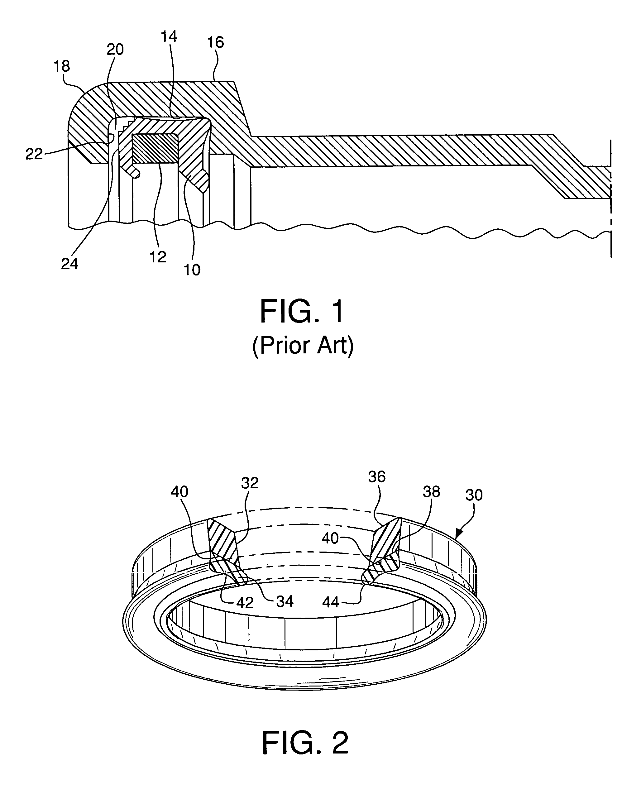
[0023]Referring now to the drawings, FIG. 1 depicts an elastomeric gasket 10, formed, for example of rubber, with a plastic retaining ring 12 formed, for example of polypropylene, disposed in the circular groove 14 of the hub 16 or belled end of a plastic pipe or fitting. Hub 16 has a bent retainer 18, which as formed by heating the end of the pipe or fitting and bending the end of the pipe with a steel bending die (not shown). As seen in FIG. 1, use of such die results in a gap 20 between the inner wall 22 of the bent retainer and the adjacent edge 24 of the elastomeric ring 10. Thus, the final position and dimensions of the bent retaining wall 18 depends entirely on the steel bending die, which resu...


PUM


Abstract

A gasketed pipe joint including a dual-functional, composite gasket, which in addition to forming a seal between a pipe bell and a spigot provides a molding surface for forming a bent retainer in the hub of the pipe or fitting. The dual-functional composite gasket comprises a first axially disposed portion formed of a non-elastomeric, substantially rigid, substantially non-resilient plastic material and has a first leading edge and a first trailing edge, and a second axially disposed portion, adjacent the first axially disposed portion, formed of an elastomeric material. Preferably, the gasket comprises a major portion of the non-elastomeric, substantially rigid, substantially non-resilient plastic and a minor portion of the elastomeric material.

Description

FIELD OF THE INVENTION[0001]The present invention relates to a fitting or pipe socket containing a dual-functional composite gasket comprising an elastomeric portion and a non-elastomeric portion for providing a securely seated gasket in the fitting so that an improved seal results between the gasketed socket and a spigot, the method of forming the fitting containing the securely sealed gasket, and the composite gasket, per se. Additionally, the present invention relates to an improved pipe joining system including the composite gasket.BACKGROUND OF THE INVENTION[0002]In plastic pipe systems, connections between the various components must be sealed to prevent escape of fluids from the connections. The connections typically comprise an enlarged bell which receives a spigot. The spigot and bell can be formed as segments of pipe lengths or connecting members, such as elbows, T's, etc. In this application, the terms “fitting” and “pipe” are intended to include both pipe lengths and con...

Claims


Application Information

Patent Timeline
Patent Type & Authority Patents(United States)
IPC IPC(8): F16L17/06F16L21/03
CPCF16L21/03
Inventor VALLS, JR., JOSE E.
Owner TIGRE USA
Why Eureka
Try Eureka