
Portable air compressor

a portable, air compressor technology, applied in the direction of piston pumps, positive displacement liquid engines, pump components, etc., can solve the problems of inconvenient use of conventional air compressors, difficult to move conventional air compressors (b>60/b>) to another location, difficult to move conventional air compressors (b>60/b>) to the second floor or outdoors, etc., to achieve convenient and easy carrying of air compressors, convenient and easy to carry

Active Publication Date: 2006-11-28
HSIAO EMING
View PDF9 Cites 21 Cited by
  • Summary
  • Abstract
  • Description
  • Claims
  • Application Information

AI Technical Summary

Benefits of technology

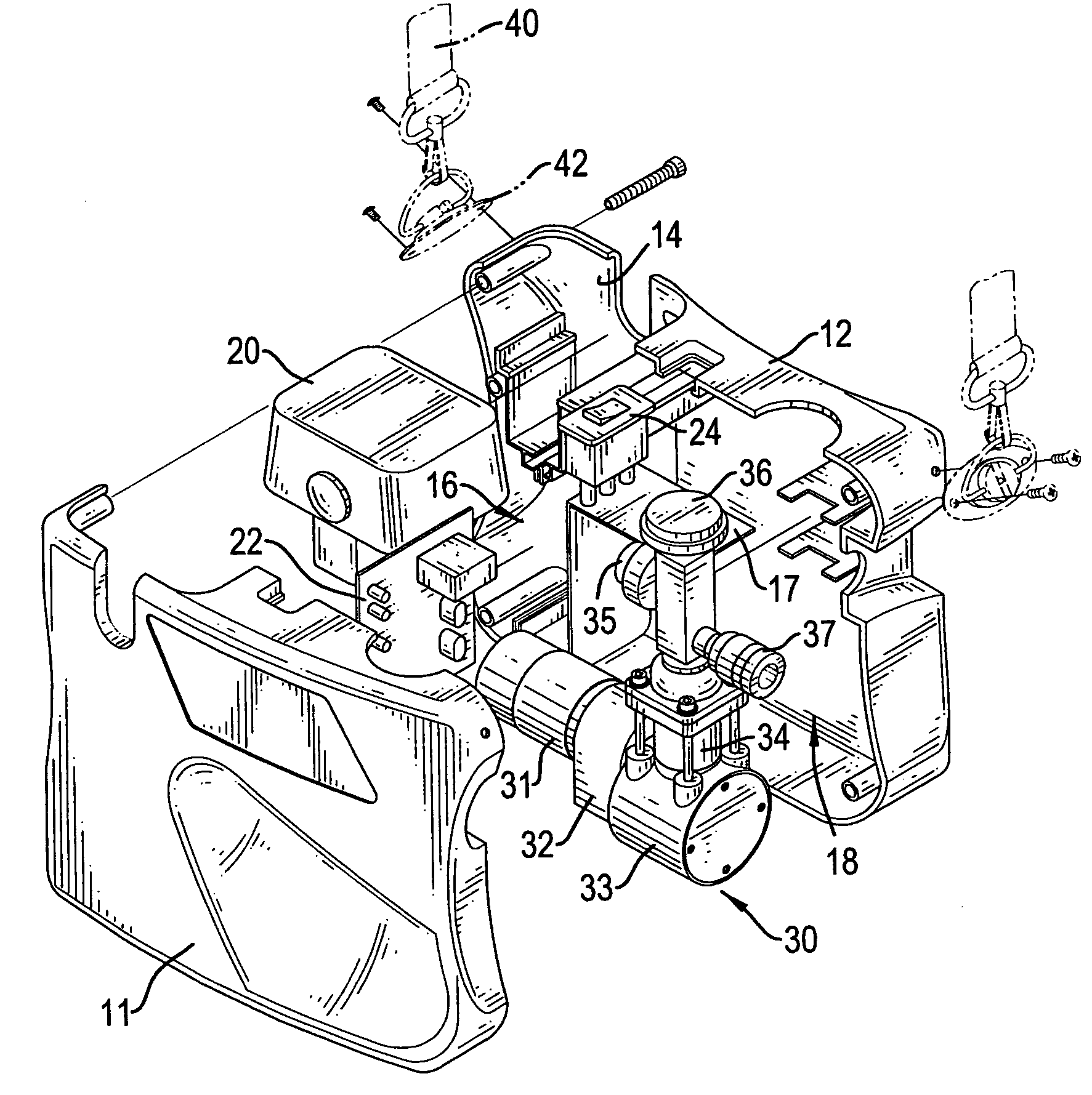
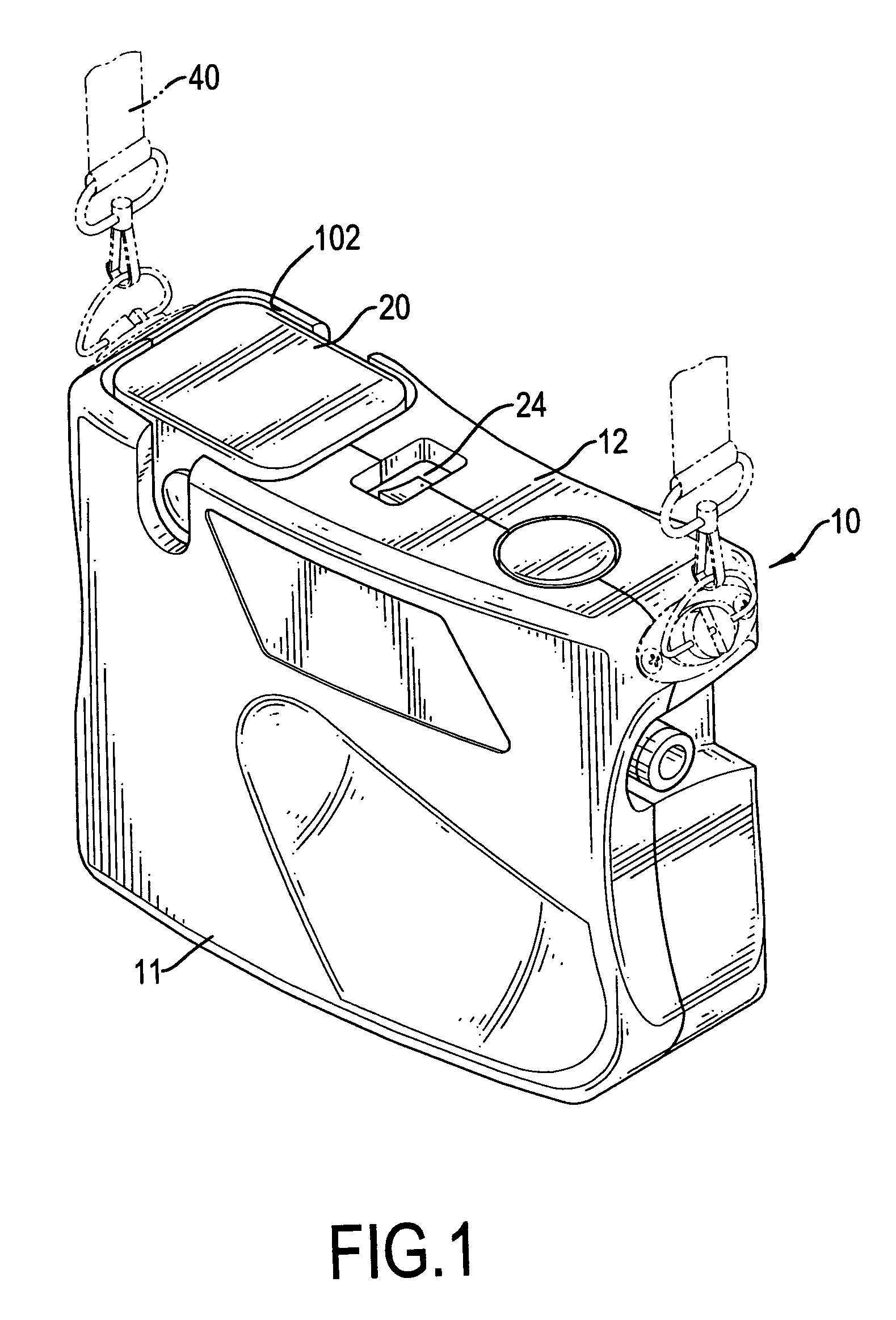
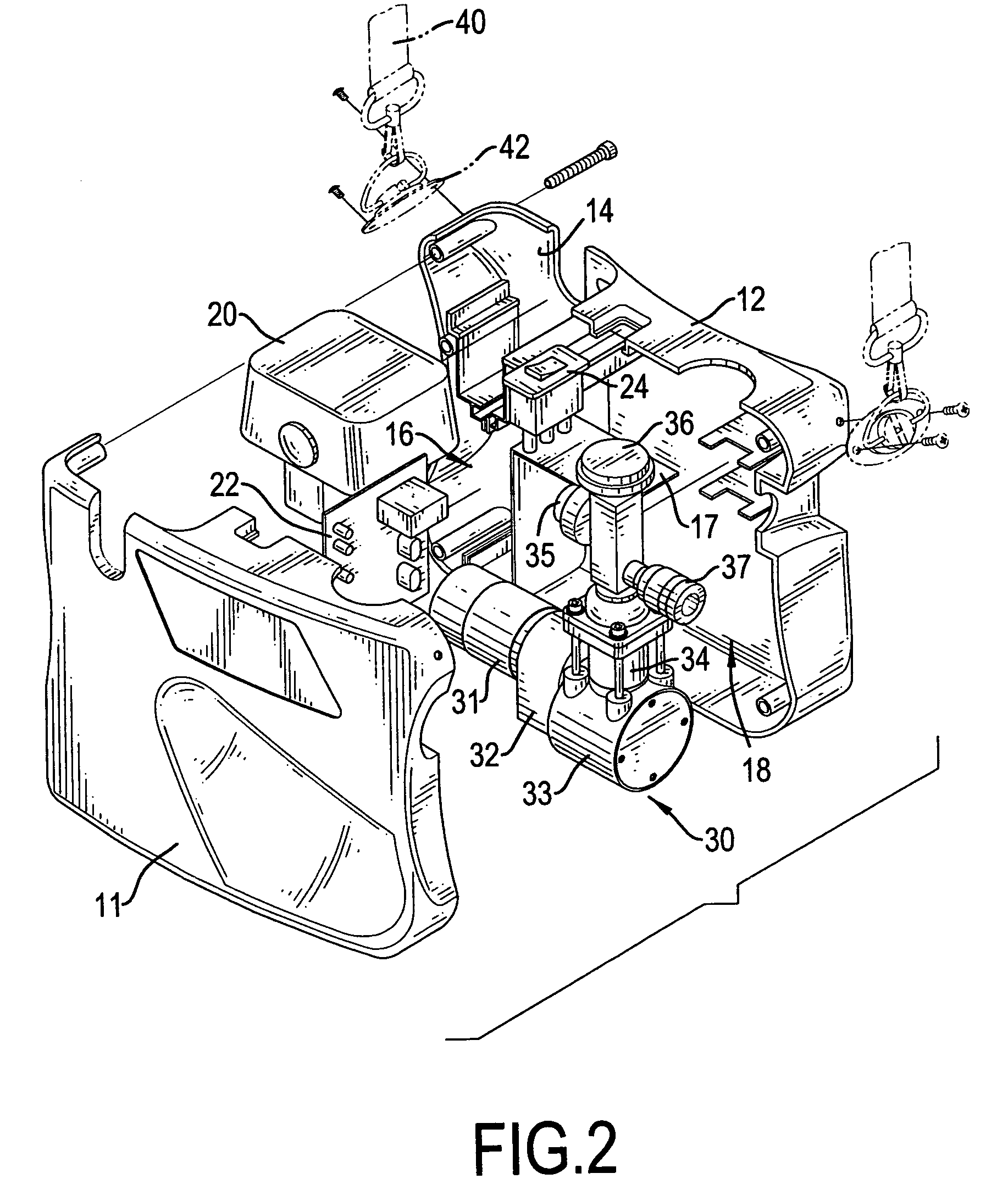
[0007]The main objective of the invention is to provide an air compressor that is conveniently and easily carried to any desired location for operation. The air compressor has a housing, a battery, a printed circuit board, a switch, an air compressing device and a belt. The housing is composed of a right cover and a left cover. A battery chamber, a printed circuit board chamber and a compressing device chamber are defined between the right and left covers to respectively receive the battery, the printed circuit board and the air compressing device. A baffle is formed in the housing between the printed circuit board chamber and the compressing chamber. The switch is mounted in and exposed from the housing and electrically connected to the printed circuit board. The belt is attached to the housing, such that a user can conveniently and easily carry the air compressor on the user's body to any desired location for use.

Problems solved by technology

However, the conventional air compressor (60) has a large volume and a heavy weight, such that to transport the conventional air compressor (60) is very difficult.
Therefore, to move the conventional air compressor (60) to another location, such as the second floor or outdoors, is difficult, and the simple though limited solution is a hose (62) with a long length.
Therefore, the conventional air compressor (60) is inconvenient in use.

Method used


Image

  • Portable air compressor
  • Portable air compressor
  • Portable air compressor

Examples


Embodiment Construction

[0016]With reference to FIGS. 1 to 3, an air compressor in accordance with the present invention comprises a housing (10), a battery (20), a printed circuit board (22), an air compressing device (30), a switch (24) and a belt (40). The housing (10) is composed of a right cover (11) and a left cover (12). The right cover (11) and the left cover (12) are combined together with bolts. The housing (10) has a battery chamber (14), a printed circuit board chamber (16) and a compressing device chamber (18) defined between the right and left covers (11, 12). The printed circuit board chamber (16) is adjacent to the battery chamber (14), and the compressing device chamber (18) is adjacent to the compressing chamber (16). The housing (10) further has an opening (102) communicating the battery chamber (14) and a baffle (17) formed in the housing (10) between the printed circuit board chamber (16) and the compressing chamber (18).

[0017]The battery (20) is received in the battery chamber (14) th...


PUM


Abstract

An air compressor has a housing, a battery, a printed circuit board, a switch, an air compressing device and a belt. The housing is composed of a right cover and a left cover. A battery chamber, a printed circuit board chamber and a compressing device chamber are defined between the right and left covers to respectively receive the battery, the printed circuit board and the air compressing device. A baffle is formed in the housing between the printed circuit board chamber and the compressing chamber. The switch is mounted in and exposed from the housing and electrically connected to the printed circuit board. The belt is attached to the housing, such that a user can conveniently and easily carry the air compressor on the user's body to any desired location for use.

Description

BACKGROUND OF THE INVENTION[0001]1. Field of the Invention[0002]The present invention relates to an air compressor, and more particularly to a portable air compressor that can be conveniently and easily carried to any desired location for use.[0003]2. Description of Related Art[0004]With reference to FIG. 7, an air compressor (60) is used to compress air to a desired high pressure, and the high-pressured air is applied to drive a pneumatic tool. A conventional air compressor (60) substantially comprises a base (not numbered) and a compressing device (not numbered) mounted on the base and for compressing air to a desired high pressure. A hose (62) is attached by one end to a connector of the compressing device and the other end is connected to a pneumatic tool. Accordingly, the high-pressured air is applied to the pneumatic tool through the hose (62).[0005]However, the conventional air compressor (60) has a large volume and a heavy weight, such that to transport the conventional air ...

Claims


Application Information

Patent Timeline
Patent Type & Authority Patents(United States)
IPC IPC(8): F04B53/00F04B35/01F04B35/04F04B35/06
CPCF04B35/01F04B35/04F04B35/06
Inventor HSIAO, EMING
Owner HSIAO EMING
Learn More