Brushless DC motor system and method of controlling the same

a brushless dc motor and motor control technology, applied in the direction of motor/generator/converter stopper, electronic commutator, dynamo-electric converter control, etc., can solve the problems of vibration and noise in the motor, the time it takes to increase the current to a desired value or to reduce the current to zero, and the disadvantage of conventional methods, so as to reduce the torque ripple

Inactive Publication Date: 2006-11-28
KOREA INST OF SCI & TECH
View PDF15 Cites 50 Cited by
  • Summary
  • Abstract
  • Description
  • Claims
  • Application Information

AI Technical Summary

Benefits of technology

[0013]Therefore, it is an object of the present invention to address and overcome the above-referenced problems of the prior art. In particular, the object of the present invention is to reduce a torque ripple, which occurs during a commutation interval, by changing a duty ratio of pulses according to a speed change of the BLDC motor.

Problems solved by technology

Also, it takes time to increase the current to a desired value or to decrease the current to zero.
The torque ripple causes vibrations and noises in the motor.
However, the conventional methods are disadvantageous since they are undesirably sensitive to the change of parameters of the BLDC motor.
Thus, the stable performance of the BLDC cannot be guaranteed at the low or high speed due to the speed change of the BLDC motor 50.

Method used


Image

  • Brushless DC motor system and method of controlling the same
  • Brushless DC motor system and method of controlling the same
  • Brushless DC motor system and method of controlling the same

Examples


Embodiment Construction

[0030]With reference to the drawings, the preferred embodiments of the present invention will be described below in detail.

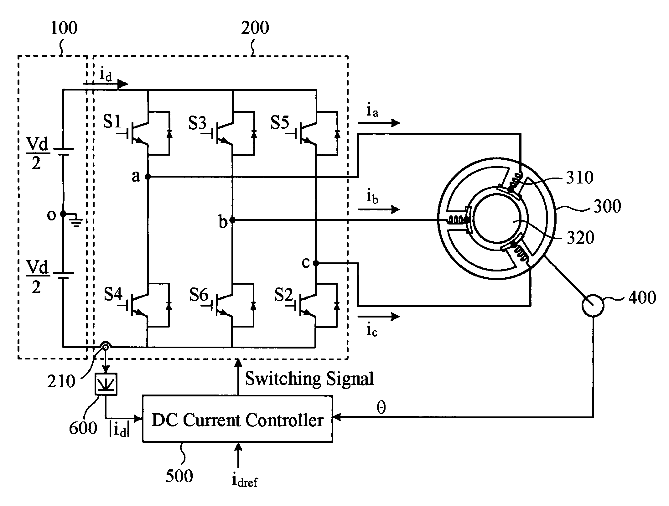
[0031]FIG. 3 is a block diagram showing a BLDC motor system for reducing a commutation torque ripple in a BLDC motor 300 constructed in accordance with a preferred embodiment of the present invention. The BLDC motor system comprises an inverter 200, a position sensor 400, a DC current controller 500 and a rectifier 600.

[0032]The BLDC motor system controls the BLDC motor 300, which includes a stator 310 and a rotator 320. The stator 310 has three coils and the rotator 320 has at least one permanent magnet surrounded by the stator 310.

[0033]The inverter 200 receives DC power from a power supply 100. It is preferable that the power supply 100 further comprises a converter (not shown) for converting AC power, which is inputted from the outside, into DC power. The inverter 200 comprises six switches S1 to S6. The switches S1 to S6 can be formed with various switching...


PUM


Abstract

A brushless DC (BLDC) motor system and a method of controlling the same are provided. The BLDC motor system comprises a BLDC motor including a rotator and a stator, a plurality of switches, a DC current sensor, a position detector and a controller. The stator has a plurality of coils to which currents having different phase are applied. The switches are driven with switching pulses for switching the currents applied to the coils. The position detector detects a position change of the rotator to thereby generate a counter-electromotive force and the DC current sensor senses currents when the currents are applied from the switches to the coils. Based on a magnitude of the counter electromotive force, the controller generates a compensation voltage in order to control the switches during the commutation interval. Further, a duty ratio of the switching pulse is controlled based on the differences between the currents applied to the coils and a reference current.

Description

FIELD OF THE INVENTION[0001]The present invention generally relates to a Brushless DC (BLDC) motor system, and more particularly to a BLDC motor system and a method of controlling the same to reduce a commutation torque ripple, which occurs during a commutation interval.BACKGROUND OF THE INVENTION[0002]Generally, a brushless DC (BLDC) motor is a type of a DC motor that does not use mechanical contacting units such as a brush and a commutator. The BLDC motor is known to use an electrical rectifier in lieu of the mechanical contacting units. A typical BLDC motor consists of two main portions, namely, a stator and a rotator. The stator is formed of a plurality of coils, which receive poly-phase currents (e.g., three-phase currents). Rotating magnetic fields are formed by the currents applied to the coils. The rotator is formed of at least one permanent magnet surrounded by the stator, wherein the rotator rotates within the stator.[0003]To rotate the BLDC motor continuously, the rotatin...

Claims


Application Information

Patent Timeline
Patent Type & Authority Patents(United States)
IPC IPC(8): H02K21/00H02K23/00H02K31/00H02P1/18H02P3/08H02P7/00
CPCH02P6/002H02P6/28
Inventor SONG, JOONG-HOCHOY, ICK
Owner KOREA INST OF SCI & TECH
Why Eureka
Try Eureka