Monitoring communications networks

a communication network and monitoring technology, applied in the field of monitoring communications networks, can solve the problems of increasing the difficulty of simplistic monitoring, requiring disruption of physical links, and additional intrusion into the operation of the network, so as to achieve the effect of reducing the overhead of monitoring the network and more efficient web broadcasts

Active Publication Date: 2006-11-28
VIAVI SOLUTIONS INC
View PDF4 Cites 25 Cited by
  • Summary
  • Abstract
  • Description
  • Claims
  • Application Information

AI Technical Summary

Benefits of technology

[0006]A facility for less intrusive monitoring is built into some commercial routers, in the form of an extra physical output that can be configured within the router to replicate the data on any one of several outgoing links, avoiding signal loss on the optical link itself. One such example is CISCO Systems' “SPAN” port (Switched Port ANalyser). Again, however, the probe apparatus receiving the replicated signal must process all of the data on the physical link, and can only monitor data travelling on one link at a time.
[0007]It is an object of the invention to provide an alternative method for more flexible probing of one or more distinct network data streams conveyed in a distributed communications network, particularly one using label switching.
[0014]At least some commercially available routers are provided with a “multi-cast” function, whereby different target destinations are considered equal priority and sent identical data by more efficient point to multipoint, rather than point-to-point protocols. This is designed for example to allow more efficient web broadcasts. The inventors have recognised that this multi-cast facility in a Label Switching Router can also be used to generate a copy of data travelling in an LSP, which can be used for many types of monitoring, without the need for physical taps, and without the disadvantages of having to monitor at the maximum speed of the interface or with other data being mixed in with the data of interest. The advantages provided using this method are that desired multiple label switched paths, carried on one or more physical links carrying other data not of interest, can be selectively monitored in a physically less intrusive manner.
[0015]A single router may serve as both monitoring station and probe interface station, which has the advantage that monitoring overhead in the network is minimised, and timing between the real data and the monitoring data is not too dissimilar. Alternatively, the monitoring station and probe interface station may be on separate routers. In this case, the data forwarded from the monitoring station must be routed through the network, and therefore represents an additional intrusion into the operation of the network. The user of the apparatus must determine whether the intrusion is so significant as to devalue the results of monitoring, or to disrupt the general operation of the network to an unacceptable degree.
[0026]The advantages provided by the features presented in the preceding paragraphs are that multiple label switched paths are selectively monitored in a physically less intrusive manner by a minimal number of probes. Also, that the solution is not tied to any particular protocol, is scalable and that the data collected by a probe is selectively aggregated to remove superfluous data prior to onward transmission to its consumer, such as the network manager.

Problems solved by technology

As communications networks have evolved it has become increasingly difficult to achieve such simplistic monitoring, due to their complexity and scale.
More significantly, the optical / electrical splitter inevitably takes power from the main signal, and requires disruption to the physical link.
Again, however, the probe apparatus receiving the replicated signal must process all of the data on the physical link, and can only monitor data travelling on one link at a time.
In this case, the data forwarded from the monitoring station must be routed through the network, and therefore represents an additional intrusion into the operation of the network.
The user of the apparatus must determine whether the intrusion is so significant as to devalue the results of monitoring, or to disrupt the general operation of the network to an unacceptable degree.
This would not be practical with tapping of physical interfaces and less simple with current methods for virtual monitoring, such as using a SPAN port.

Method used


Image

  • Monitoring communications networks
  • Monitoring communications networks
  • Monitoring communications networks

Examples


Embodiment Construction

[0035]This invention is not specifically limited to embodiment in either hardware or software. The following description is generally valid for either implementation, special differences being pointed out as required. The mixture of hardware and software, which is used in a given application will depend on many factors familiar to the skilled person. Such factors include the bandwidth of the network, the complexity of the monitoring tasks, the suitability of the hardware available at the time for the tasks required, the relative development costs of the different solutions, and the expected scale of production.

Background to Label Switching

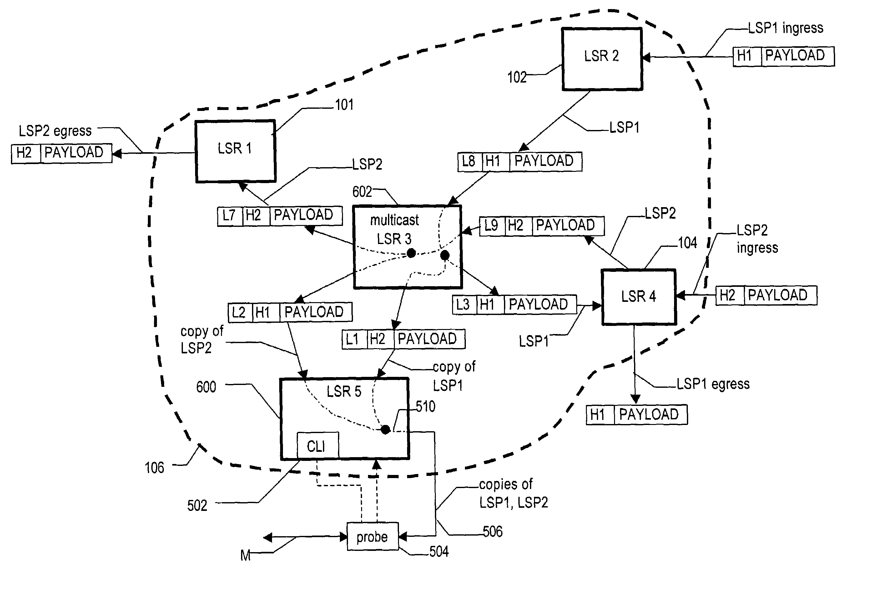
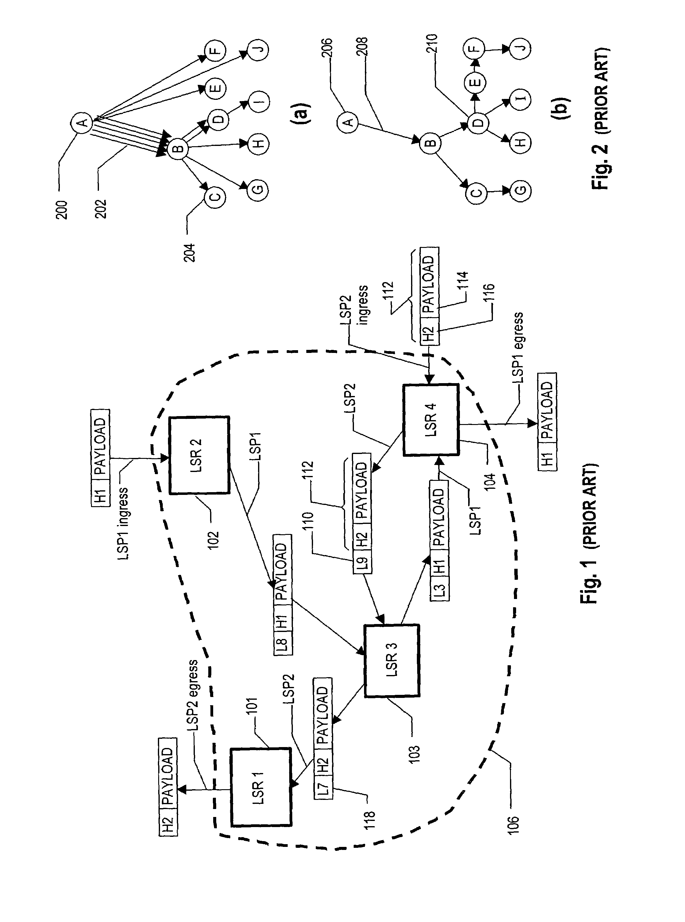
[0036]FIG. 1 shows a small label switching communications network comprising Label Switching Routers LSR1101, LSR2102, LSR3103& LSR4104, interconnected by physical links (not shown explicitly in the diagram) that carry virtual links known as Label Switched Paths (LSPs) LSP1, LSP2. A collection of LSRs and links is known as an ‘LSR cloud’106, the ou...


PUM


Abstract

Selected data (LSP1, LSP2) is monitored among other data passing through label switched paths (LSPs) of a communications network of interconnected label switching routers (LSR–LSR4). The method comprises designating at least one of the routers (LSR3) as a monitoring station and at least one of the routers (here LSR3 also) as a probe interface station, and connecting a probe apparatus to that interface station. The monitoring station (LSR3) is configured to multicast forward the selected data for monitoring additionally to the probe apparatus via the probe interface (506). Also disclosed is a probe apparatus including means for configuring the router to perform multicast forwarding of selected data to the interface.

Description

INTRODUCTION[0001]The present invention relates to a method and apparatus for selectively monitoring data streams in a connection-oriented communications network. The invention may be deployed semi-permanently to achieve a continual overview of the state of the communications system, to meter traffic flow, or, in a trouble-shooting capacity, applied at specific locations to pinpoint points of failure.[0002]A communications network is created by the connection of the transportation medium to all of the devices that access it by dedicated traffic management components. Traffic may have to flow through tens or even hundreds of such devices to reach its final destination. At a very simplistic level these network components predominantly comprise routers (which are “intelligent” versatile devices that ensure that the traffic flowing through them reach the next onward hop in an efficient and effective manner) and switches (which, although also managing traffic flow across the network, do ...

Claims


Application Information

Patent Timeline
Patent Type & Authority Patents(United States)
IPC IPC(8): H04B3/20H04L45/50
CPCH04L43/0894H04L43/12H04L45/50H04L43/026H04L43/062H04L43/0829H04L43/0847H04L43/0852
Inventor MITCHELL, KEVIN
Owner VIAVI SOLUTIONS INC
Why Eureka
Try Eureka