Optical backplane system

a backplane and optical technology, applied in the field of fiber optics, can solve the problems of limiting affecting the scalability of the system, and occupying more human errors

Active Publication Date: 2006-11-28
INTELLAMBDA SYST +1
View PDF6 Cites 4 Cited by
  • Summary
  • Abstract
  • Description
  • Claims
  • Application Information

AI Technical Summary

Problems solved by technology

However, as the optical system is getting larger and complicated, there may not be enough space on the front to allow such interconnections.
In addition, such a configuration limits the scalability of the system and may involve more human errors while wiring the modules.
Furthermore, the wire or fiber shuffling within the modules may be more expensive.

Method used


Image

  • Optical backplane system
  • Optical backplane system
  • Optical backplane system

Examples


Embodiment Construction

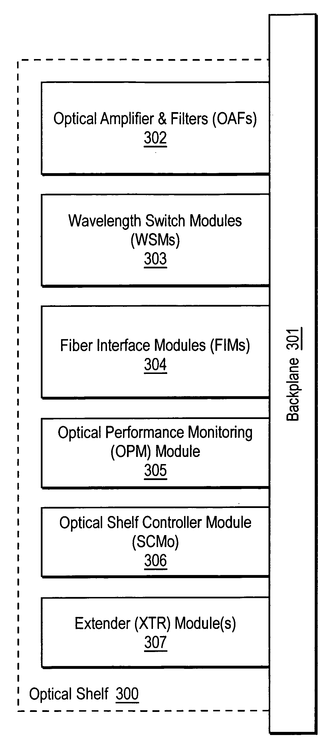
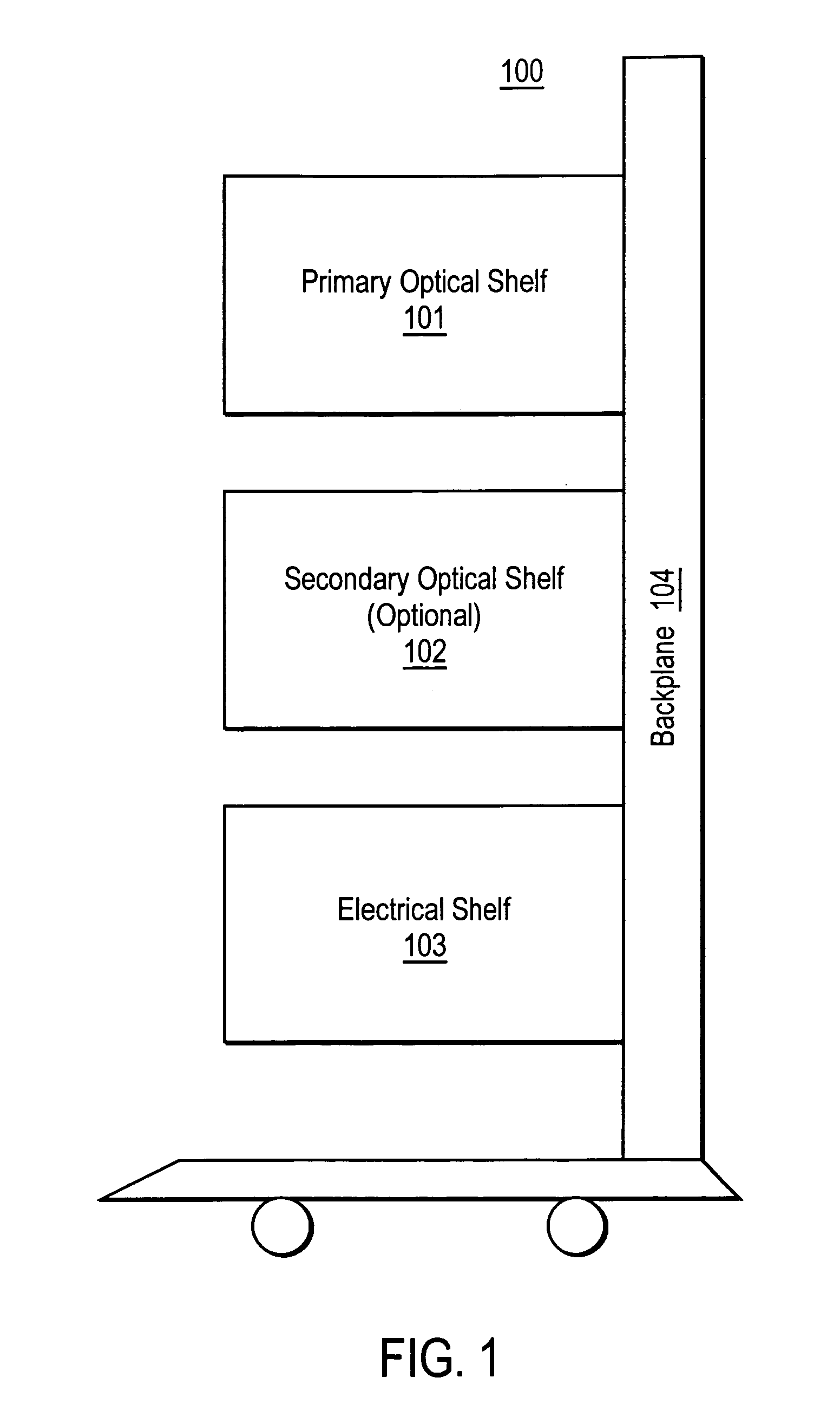
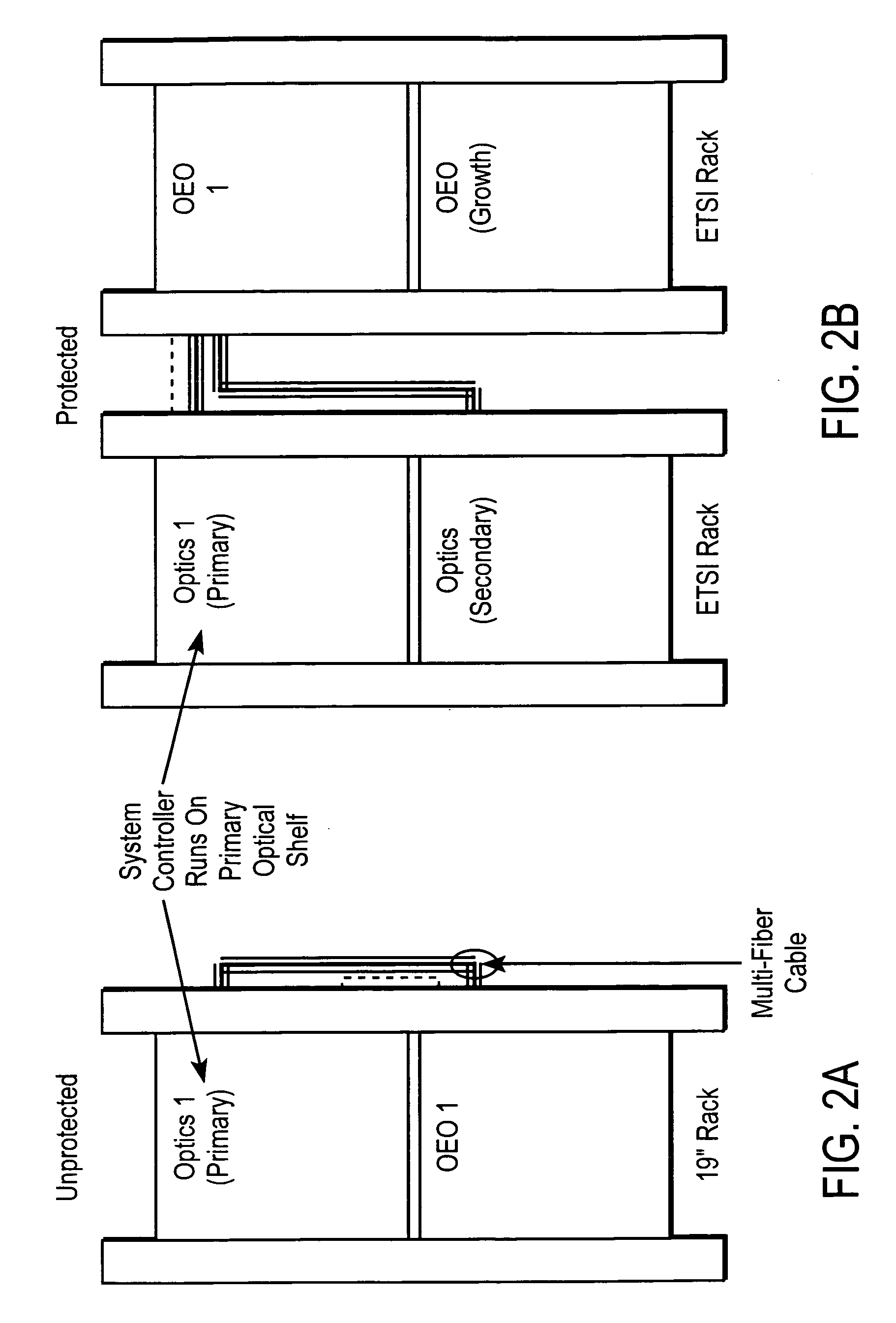
[0022]An optical backplane system is described herein. In the following description, numerous specific details are set forth (e.g., such as logic resource partitioning / sharing / duplication implementations, types and interrelationships of system components, and logic partitioning / integration choices). However, it is understood that embodiments of the invention may be practiced without these specific details. In other instances, well-known circuits, software instruction sequences, structures and techniques have not been shown in detail in order not to obscure the understanding of this description.

[0023]References in the specification to “one embodiment”, “an embodiment”, “an example embodiment”, etc., indicate that the embodiment described may include a particular feature, structure, or characteristic, but every embodiment may not necessarily include the particular feature, structure, or characteristic. Moreover, such phrases are not necessarily referring to the same embodiment. Furthe...


PUM


Abstract

An optical backplane system is described herein. In one embodiment, an exemplary system includes a backplane to interconnect multiple optical modules, multiple fiber interface modules (FIMs) having a back end inserted into multiple slots of the backplane respectively, each FIM having a front end to receive an incoming fiber carrying incoming optical signals and an outgoing fiber carrying outgoing optical signals from and to an optical network. The back end of the FIM extends the incoming and outgoing fibers to at least one of the multiple optical modules mounted via the backplane without significantly processing of the incoming and outgoing optical signals. Each of the fibers is capable of carrying multiple wavelengths of optical signals. Other methods and apparatuses are also described.

Description

FIELD OF THE INVENTION[0001]This application claims the benefit of U.S. Provisional Patent Application No. 60 / 608,570, filed Sep. 9, 2004, which is incorporated by reference herein in its entirety.FIELD OF THE INVENTION[0002]The present invention relates generally to fiber optics. More particularly, this invention relates to an optical backplane system.BACKGROUND OF THE INVENTION[0003]An optical backplane is a structure having a variety of connectors facilitating the interconnection and communication of different systems and components. More specifically, the optical backplane is configured for the interconnection of systems and components having high bandwidth optical interfaces. Conventional optical backplanes, however, also can include electrical connections and suitable interface circuitry for interconnecting systems and components having electrical interfaces.[0004]Modules or components of a conventional optical backplane include a lot of interconnections at the front of the mo...

Claims


Application Information

Patent Timeline
Patent Type & Authority Patents(United States)
IPC IPC(8): G02B6/28G02B6/00
CPCG02B6/43H04B10/801H04J14/02H04J14/0221H04Q11/0005H04Q1/155H04J14/021H04J14/0212H04Q2011/0052H04Q2201/804
Inventor LOOK, CHRISTOPHER M.
Owner INTELLAMBDA SYST
Why Eureka
Try Eureka