Pressure sensor

a technology of pressure sensor and housing, which is applied in the direction of fluid pressure measurement using elastically deformable gauges, measuring devices, instruments, etc., can solve the problems of complex installation of pressure sensor into housing, difficult to design the housing as one piece, and complicated construction of pressure sensor

Inactive Publication Date: 2006-12-05
GRUNDFOS
View PDF6 Cites 2 Cited by
  • Summary
  • Abstract
  • Description
  • Claims
  • Application Information

AI Technical Summary

Benefits of technology

[0003]It is the object of the invention to provide an improved pressure senor which has a simplified construction and is simpler to integrate into a housing, and which may be applied with corrosive liquids and gases.
[0010]Preferably both holding elements are connected to one another via at least one locking connection. This permits a very simple assembly since no additional connecting elements or adhesives are required. Such locking connections, in particular in holding elements manufactured of plastic, may be formed very simply as locking lugs or locking hooks which engage on the respective other holding element into a corresponding opening.
[0013]In a particularly preferred embodiment, at least one holding element is formed by a circuit board. Further electronic components for example for transmission, evaluation and / or processing of a measurement signal produced by the measurement element may be arranged on this circuit board. The circuit board has a double function, on the one hand it carries the electronic components and on the other hand it simultaneously serves as a holding element for the sealing element. In this manner the number of required components is reduced.
[0015]It is also preferred for gaps which preferably extend parallel to the diaphragm surface, and which extend from the through-hole to the outer periphery of the diaphragm to be formed between the contact locations between the diaphragm and the circuit-board. These gaps, between individual contact locations, connect the inside of the through-hole to the atmosphere at the outer periphery of the diaphragm. These gaps may be produced by way of the contact locations having a certain construction height so that the diaphragm is arranged distanced to the surface of the holding element or the circuit board. Thus free spaces arise between the individual contact locations, which form the interconnected gaps. The gaps serve for venting the space between the sealing element and the through-hole. This has the advantage that in the case that the sealing element should not be completely diffusion-proof and fluid, in particular moisture reaches the rear side of the sealing element, this may exit through the gaps towards the atmosphere. With this, the accumulation of moisture in the inside of the pressure sensor at the rear sides of the sealing element which are distant to the passage of fluid is prevented. The sealing element is vented to the rear via the gaps so that moisture which possibly enters through the sealing element may exit towards the outside.
[0018]Advantageously, at least the part of the sensor housing contacted by fluid is designed as one piece. At the same time the part of the sensor housing contacted by fluid is that part in which the diaphragm with the holding elements is arranged, i.e., that part in which the connection holes are formed for impinging the diaphragm with pressure. It is advantageously to design in particular this part, through which a fluid is led to the diaphragm, as one piece since further seals for sealing a multi-part sensor housing then become superfluous. The whole sensor housing is furthermore preferably designed as one piece which permits an economical manufacture of the sensor housing.

Problems solved by technology

As a whole, the construction of the pressure sensor is quite complicated, and the installation of the pressure sensor into a housing is complicated on account of the necessary arrangement of further sealing elements.
Since additional sealing elements must be intermediately mounted between the mounting and the housing, it is furthermore not possible to design the housing as one piece.

Method used


Image

  • Pressure sensor
  • Pressure sensor
  • Pressure sensor

Examples


Embodiment Construction

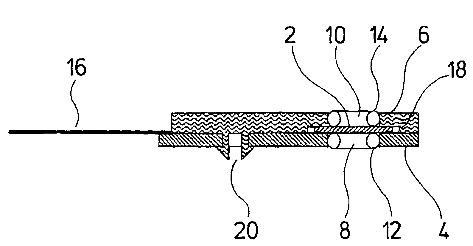
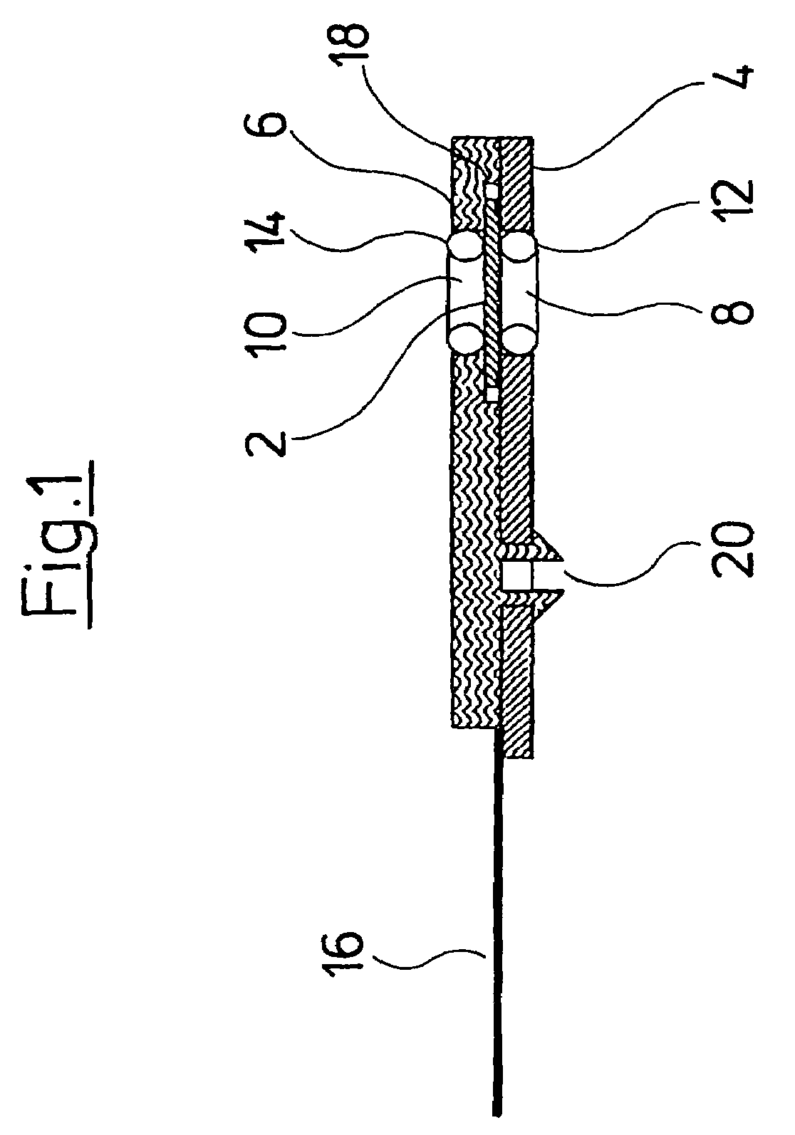
[0029]FIG. 1 shows a sectioned view of a part of the pressure sensor according to the invention. The pressure sensor comprises a diaphragm 2 on which at least one measurement element is formed for detecting a pressure. For pressure detection the diaphragm 2 is designed as is described in the European Patent application 97 105 396.2. The pressure detection is effected via the deflection of the diaphragm 2 which is detected via the measurement elements arranged on the diaphragm 2. The diaphragm 2 is arranged between two holding elements 4 and 6. Two through-holes 8 and 10 which are flush with one another are formed in the two holding elements 4 and 6. The through-holes 8 and 10 serve for fixing two sealing rings in the form of O-rings 12 and 14. The holding element 14 is designed as a circuit board on which further electronic or electrical components or connections are arranged, in order to transmit and / or process the signals produced by the measurement elements arranged on the diaphr...


PUM

PropertyMeasurementUnit
sizeaaaaaaaaaa
thicknessaaaaaaaaaa
pressureaaaaaaaaaa

Abstract

This invention relates to a pressure sensor comprising a diaphragm and at least one measuring element, which is situated on the diaphragm while serving to measure a deflection of the diaphragm. A holding element is placed on at least one surface of the diaphragm in order to accommodate a seal element, whereby this holding element has a through hole, which faces the diaphragm surface while having a cross-section that corresponds to the outer contour of a seal element to be accommodated.

Description

BACKGROUND OF THE INVENTION[0001]The invention relates to a pressure sensor.[0002]A pressure or differential pressure sensor is known from the European Patent application 97 105 396, with which a diaphragm with a measurement element located thereon is applied. The diaphragm is formed in a carrier which is sealingly clamped or bonded into a two-part mounting. The measurement element on the membrane, via electrical leads, is connected to further electronic components arranged on a circuit board, wherein the circuit board is fastened distanced to the carrier on a part of the mounting. Through-holes are formed in each case in the two parts of the mounting, in order to impinge the diaphragm with pressure. At the same time, the two parts of the mounting must be brought into sealing contact with outer connection channels to a housing. Additional sealing elements are required for this. As a whole, the construction of the pressure sensor is quite complicated, and the installation of the pres...

Claims


Application Information

Patent Timeline
Patent Type & Authority Patents(United States)
IPC IPC(8): G01L9/06G01L7/08G01L9/00
CPCG01L9/0048G01L9/0051
Inventor MIKKELSEN, STEENANDERSEN, PERKROG, JENS PETER
Owner GRUNDFOS
Why Eureka
Try Eureka