Control apparatus

a control apparatus and control technology, applied in the direction of adaptive control, electric control, instruments, etc., can solve the problems of low control accuracy, low control resolution, and high friction of the above-mentioned hydraulically-driven variable cam phase mechanism as a controlled object, and achieve high levels of control resolution and control accuracy

Inactive Publication Date: 2006-12-05
HONDA MOTOR CO LTD
View PDF2 Cites 10 Cited by
  • Summary
  • Abstract
  • Description
  • Claims
  • Application Information

AI Technical Summary

Benefits of technology

[0011]The present invention has been made to provide a solution to the above-described problem, and an object thereof is to provide a control apparatus that is capable of maintaining both the control resolution and the control accuracy at respective high levels even when at least one of the nonlinearity and the frequency characteristic of a controlled object varies.
[0015]With the configuration of the preferred embodiment, the control input is calculated based on a value formed by modulating one of a plurality of input components obtained by dividing the follow-up control input, and the other input components. Therefore, even when there occurs a state in which the controlled variable largely deviates from the target value, and the range of variation in the follow-up control input is large, by properly setting the amplitude of the value formed by modulating the one input component, it is possible to prevent the amplitude of the control input from becoming excessively large, to thereby cause the controlled variable to follow the target value while preventing the inverting state of the control input from being reflected in the controlled variable in a noise-like fashion. As a result, it is possible to further enhance the control resolution and the control accuracy.
[0017]With the configuration of the preferred embodiment, the control input is calculated by modulating the follow-up control input with algorithms including a modulation algorithm based on a ΔΣ modulation algorithm, a ΣΔ modulation algorithm, or a Δ modulation algorithm. In this case, all of the ΔΣ modulation algorithm, the ΣΔ modulation algorithm, and the Δ modulation algorithm have a characteristic that as a value input thereto becomes closer to a value of 0, the inverting frequency of a value calculated therewith become higher. On the other hand, the follow-up control input is a value for controlling the controlled variable such that it is caused to follow the target value, and hence as the controlled variable becomes closer to the target value, the follow-up control input undergoes a less change. Therefore, by configuring the modulation algorithm based on one of the ΔΣ modulation algorithm, the ΣΔ modulation algorithm, or the Δ modulation algorithm, such that when the follow-up control input undergoes less or almost no change, the value input to the one of the ΔΣ modulation algorithm, the ΣΔ modulation algorithm, and the Δ modulation algorithm becomes close to a value of 0, it is possible to calculate the control input such that as the controlled variable becomes closer to the target value, the inverting frequency of the control input becomes higher. As a result, it is possible to improve the convergence of the controlled variable to the target value, compared with the case in which the phase control input is calculated by PWM or dithering with a fixed inverting frequency.
[0019]With the configuration of the preferred embodiment, when the phase of the intake camshaft and / or the exhaust camshaft relative to the crankshaft is controlled by the control input, it is possible to maintain the control resolution and the control accuracy at respective high levels, as described hereinabove.
[0021]With the configuration of the preferred embodiment, when the lift of the intake valves and / or the exhaust valves is controlled by the control input, it is possible to maintain the control resolution and the control accuracy at respective high levels, as described hereinabove.
[0023]With the configuration of the preferred embodiment, when the air-fuel ratio parameter indicative of the air-fuel ratio of a mixture supplied to the engine is controlled by the control input, it is possible to maintain the control resolution and the control accuracy at respective high levels, as described hereinabove.

Problems solved by technology

It is generally known that the above-mentioned hydraulically-driven variable cam phase mechanism as a controlled object is high in friction, and is strong in nonlinearities, such as hysteresis and dead time.
However, the control apparatus of Japanese Laid-Open Patent Publication (Kokai) No. 2001-132482 calculates the control input with the sliding mode control algorithm, and hence when the controlled object with strong nonlinearities, i.e. the hydraulically-driven variable cam phase mechanism is controlled, due to the strong nonlinearities, it is impossible to control the cam phase by the control input up to a slight degree of change, resulting in low control resolution and low control accuracy.
Further, when oil pressure is supplied to the hydraulically-driven variable cam phase mechanism from an oil pump using the torque of the engine as a drive source, variation in the engine speed causes variation in the oil pressure supplied to the variable cam phase mechanism, which causes variation in the frequency characteristic and the nonlinearity of the cam phase with respect to the control input.
Therefore, if the nonlinearity and frequency characteristic vary, the repetition period deviates from the proper value, which causes the inverting behavior of the control input to be reflected in the cam phase in a noise-like fashion, or makes the control system unstable (resonant).

Method used


Image

  • Control apparatus
  • Control apparatus
  • Control apparatus

Examples


first embodiment

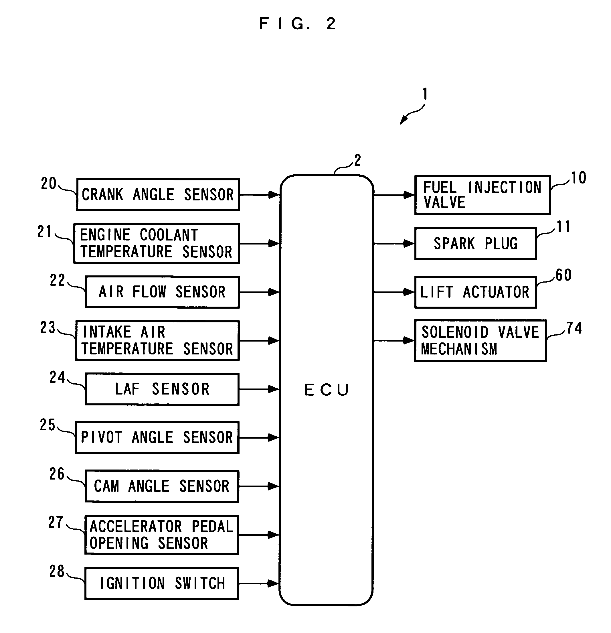
[0054]Hereafter, a control apparatus for an internal combustion engine, according the present invention, will be described with reference to the drawings. As shown in FIG. 2, the control apparatus 1 includes an ECU 2. As described hereinafter, the ECU 2 carries out various control processes for controlling a cam phase, a valve lift, etc., depending on operating conditions of an internal combustion engine (hereinafter simply referred to as “the engine”) 3.

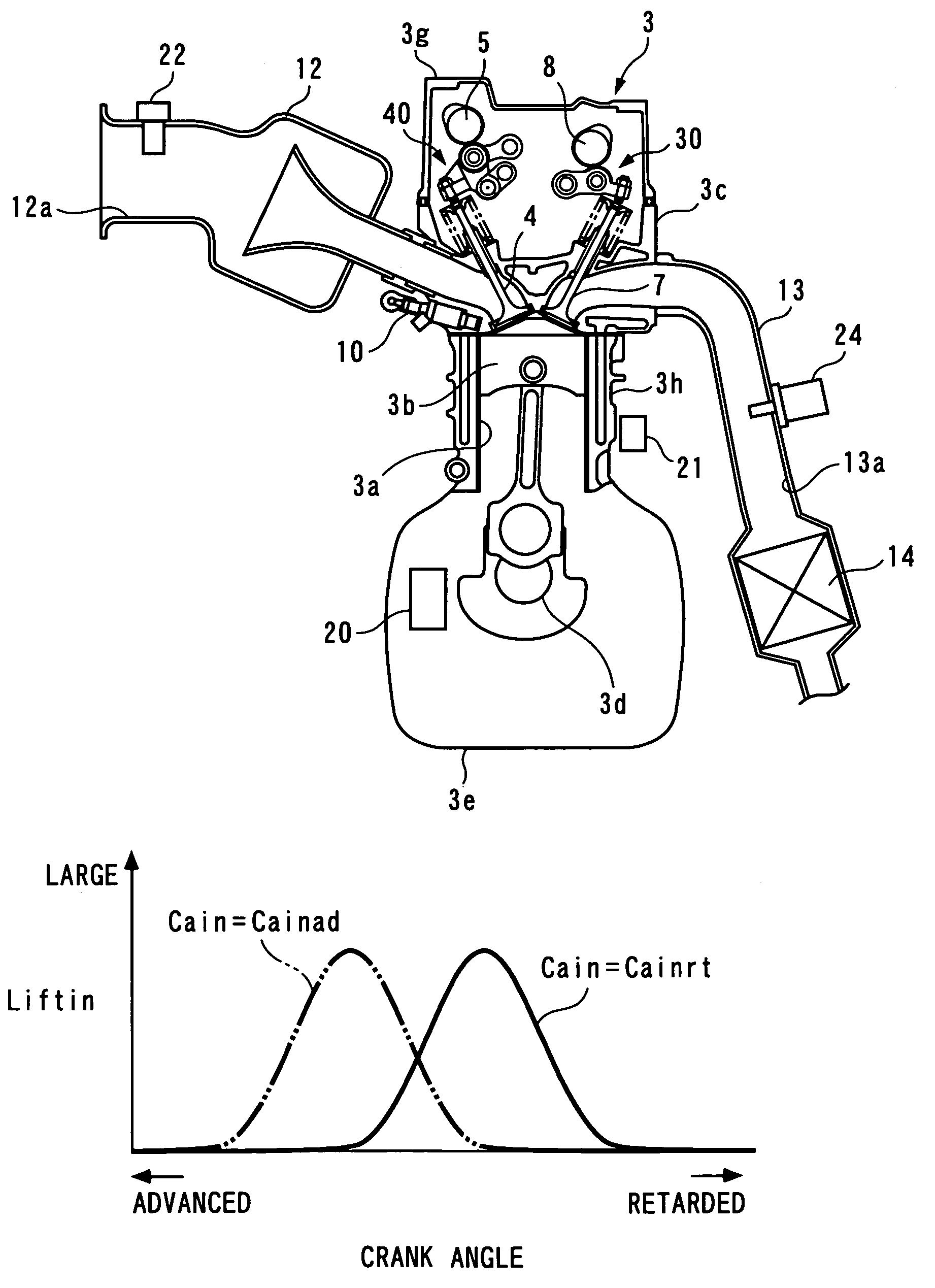
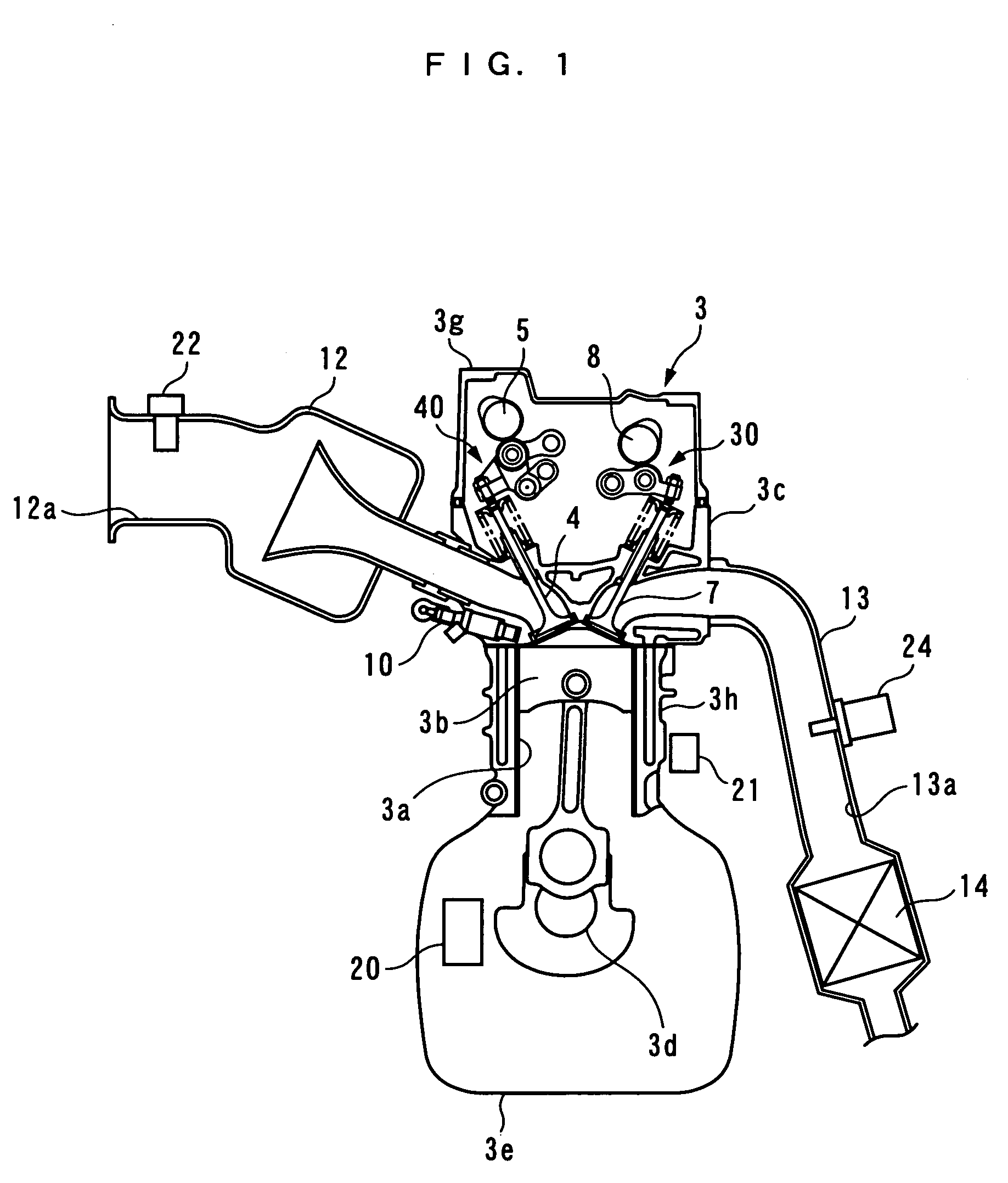
[0055]Referring to FIGS. 1 and 3, the engine 3 is an in-line four-cylinder gasoline engine having a four pairs of cylinders 3a and pistons 3b (only one pair of which is shown), and installed on a vehicle, not shown. The engine 3 includes an intake valve 4 and an exhaust valve 7 provided for each cylinder 3a, for opening and closing an intake port and an exhaust port thereof, respectively, an intake camshaft 5 and intake cams 6 for actuating the intake valves 4, a variable intake valve-actuating mechanism 40 that actuates the intake ...


PUM


Abstract

A control apparatus that is capable of maintaining both the control resolution and the control accuracy at respective high levels even when at least one of the nonlinearity and the frequency characteristic of a controlled object varies. A control apparatus 1 that control a cam phase Cain by a phase control input Ucain includes two controllers 102 and 103. The two-degree-of-freedom response-specifying controller 102 calculates a follow-up control input Rsld as a value for causing the cam phase to follow a target cam phase Cain_camd. The DSM controller 103 calculates a phase control input Ucain by modulating the follow-up control input Rsld, and in the calculation, the repetition period at which the phase control input Ucain is calculated is selected from two repetition periods ΔT1 and ΔT2 according to engine speed NE, a cam phase Cain, and a valve lift Liftin.

Description

[0001]This application claims priority under 35 U.S.C. § 119(a) to Japanese Patent Application No. 152582 / 2005, filed on May 25, 2005.BACKGROUND OF THE INVENTION[0002]1. Field of the Invention[0003]The present invention relates to a control apparatus that controls a controlled object which varies in nonlinearities, such as hysteresis and dead time, and frequency characteristic.[0004]2. Description of the Related Art[0005]Conventionally, there has been proposed a control apparatus that controls a variable cam phase mechanism as in Japanese Laid-Open Patent Publication (Kokai) No. 2001-132482. The variable cam phase mechanism varies the phase of an intake camshaft relative to a crankshaft of an internal combustion engine (hereinafter referred to as “the cam phase”) as desired, and is hydraulically driven by oil pressure supplied from an oil pump. Further, the control apparatus includes a crank angle sensor and a cam angle sensor that detect respective signals corresponding to angular ...

Claims


Application Information

Patent Timeline
Patent Type & Authority Patents(United States)
IPC IPC(8): F01L1/34
CPCF01L1/34F01L1/3442F01L13/0021F02D13/0211F02D13/0219F02D41/0002F02D41/1401G05B13/02F01L2800/00F02D2041/001Y02T10/42Y02T10/18Y02T10/12Y02T10/40
Inventor YASUI, YUJI
Owner HONDA MOTOR CO LTD
Why Eureka
Try Eureka