Apparatus for a vehicle for protection of a colliding object

a technology for protecting objects and vehicles, applied in vehicular safety arrangments, electric devices, process and machine control, etc., can solve the problems of not being able to provide a sufficient cushion to absorb the impulsive force of pedestrians, not being able to provide a sufficient absorber effect, and not being able to provide a sufficient cushion

Inactive Publication Date: 2006-12-05
HONDA MOTOR CO LTD
View PDF17 Cites 44 Cited by
  • Summary
  • Abstract
  • Description
  • Claims
  • Application Information

AI Technical Summary

Benefits of technology

[0011]The apparatus of the present invention described above deploys the air bag on either the hood of the vehicle or the outside of the windshield when it predicts or detects the collision. The apparatus simultaneously takes the forward image of the vehicle and automatically displays it on the monitor disposed in the cabin. In this way, even if the deployed air bag occupies the windshield and blocks the view of a driver, the monitor on which the forward image of the vehicle is displayed can provide the virtual forward view for the driver. This removes restrictions from the size of air bag, thereby enabling an arbitrary increase in the size, so that the performance of air bag in terms of cushion is enhanced. Therefore, the apparatus, which employs the air bag for absorbing the impulsive force acting on the colliding object, can serve as an effective protector.
[0013]The apparatus described above, which employs the head-up display unit serving as a monitor, can automatically project a forward image of vehicle taken by the camera on the windshield in front of a driver. In this way, the apparatus can provide the driver with the forward view, not changing the line of sight of the driver, when a collision between the vehicle and a pedestrian occurs.

Problems solved by technology

The hood air bag apparatus disclosed in Japanese Published Patent Application 8-183422, in which the thickness of an air bag is about 100 to 200 mm when it is deployed, is not able to sufficiently absorb the impulsive force acting on the pedestrian.
On the other hand, the collision absorber apparatus of hood-elevated type, whose elevated distance at the backward distal portion of hood is about 100 mm, is not able to provide a sufficient cushion to absorb the impulsive force.
These conventional techniques have a common problem that they cannot provide sufficient absorber effect during medium to high speed traveling of a vehicle because they are short of performance in terms of cushion.
However, because each modification leads to an increase in the size of the apparatus, it may be difficult to adopt it, taking into account an ever-growing component density in an engine room.
There is also another problem that if the size of air bag or the elevated distance is increased, the view of a driver is blocked because the air bag or the hood confronts the windshield.

Method used


Image

  • Apparatus for a vehicle for protection of a colliding object
  • Apparatus for a vehicle for protection of a colliding object
  • Apparatus for a vehicle for protection of a colliding object

Examples


first embodiment

a. First Embodiment

[0026]An apparatus for a vehicle for protection of a colliding object according to a first embodiment is described referring to FIGS. 1 through 6C.

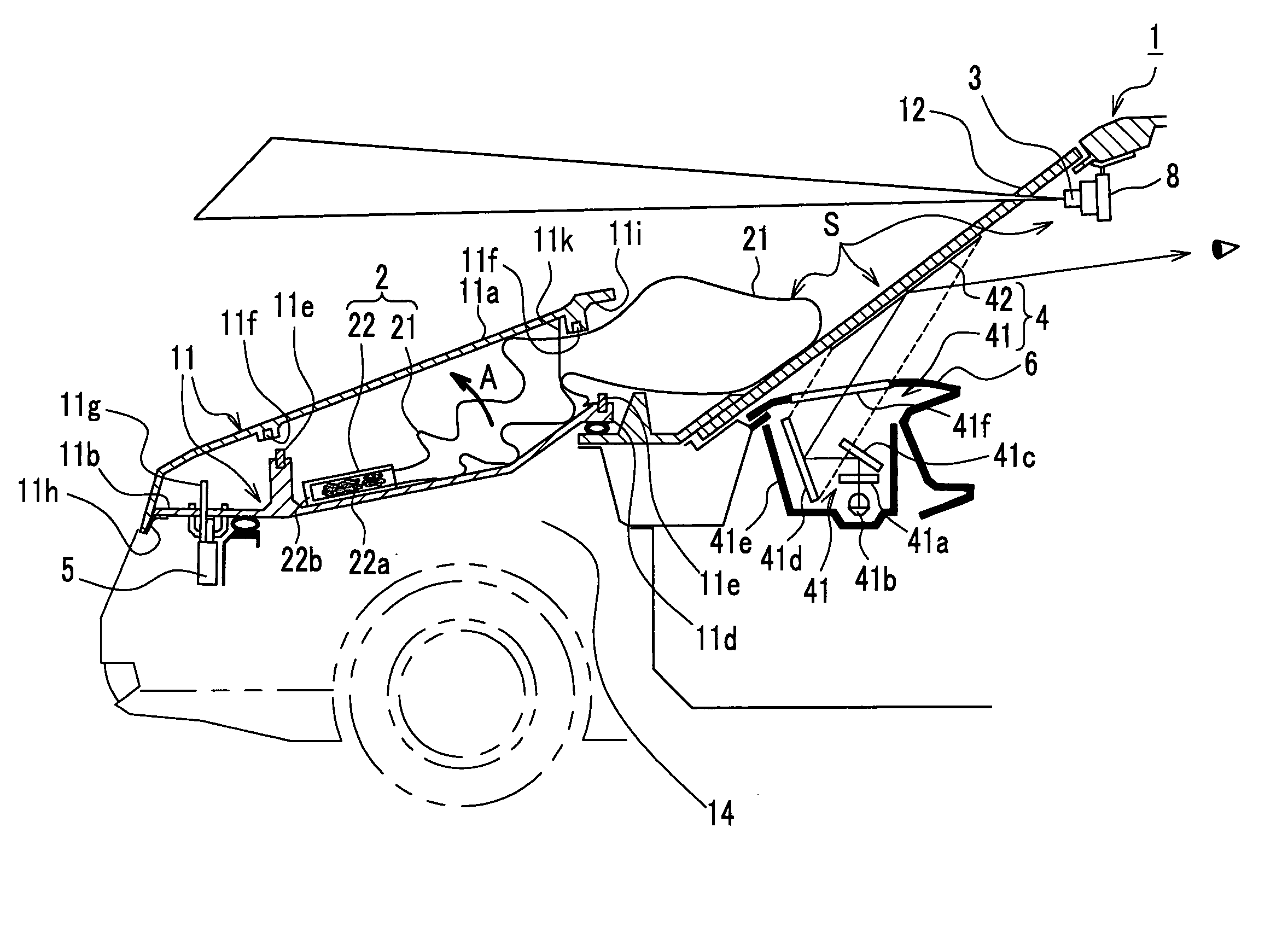
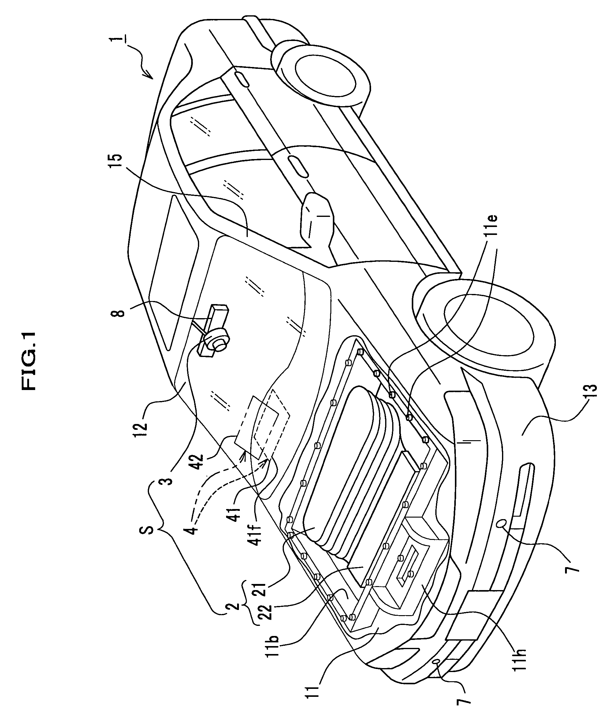
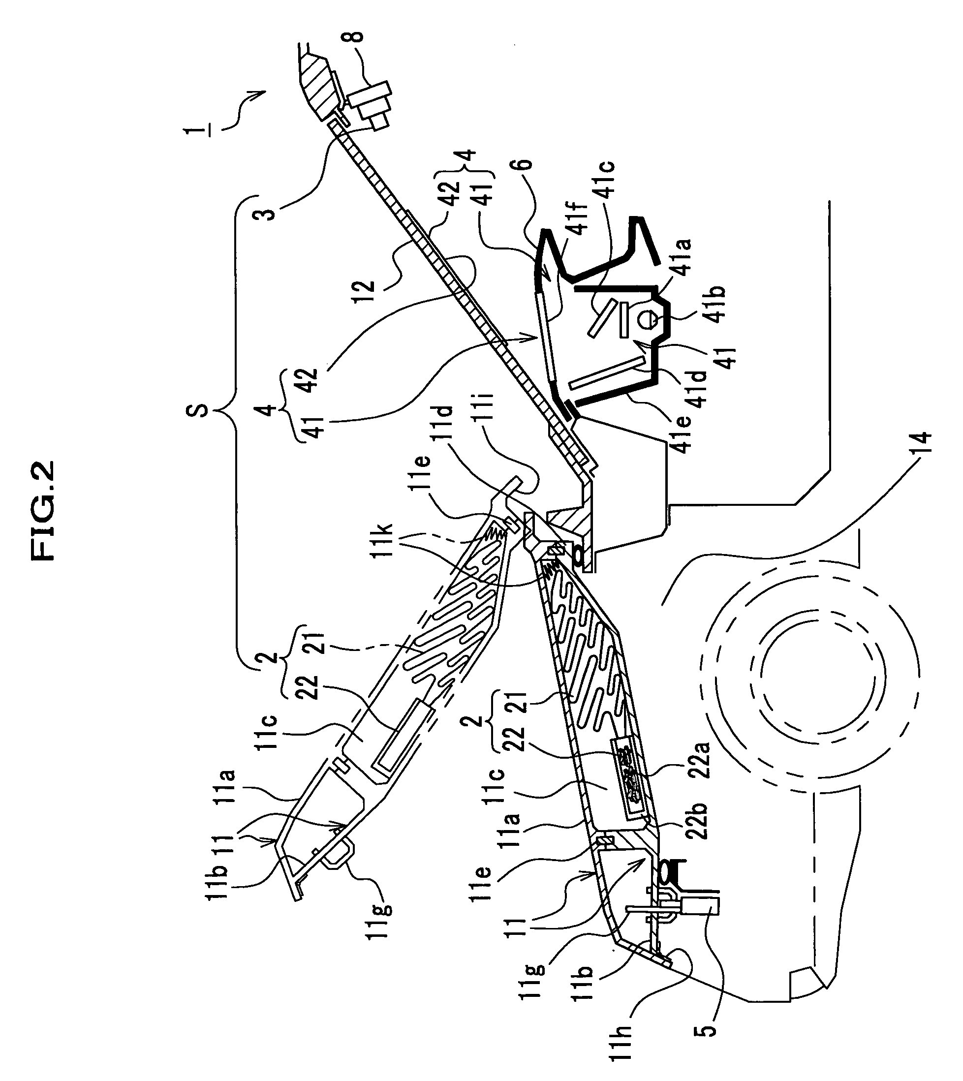
[0027]As shown in FIG. 1, an apparatus S for a vehicle for protection of a colliding object (hereinafter referred to as “apparatus S”) includes a pedestrian sensor 7, an air bag unit 2, a camera 3 for taking a forward image of a vehicle and a monitor 4. The pedestrian sensor 7 predicts the potential for a collision by detecting a distance L between a vehicle body 1 and a pedestrian H and the velocity of vehicle 1. Receiving a precautionary signal from the pedestrian sensor 7, the air bag unit 2 deploys an air bag 21. Similarly, receiving the precautionary signal from the pedestrian sensor 7, the monitor 4 displays the image taken by the camera 3. The apparatus S deploys the air bag 21 on either a hood 11 of the vehicle or the outside of a windshield 12 when the pedestrian sensor 7 predicts the potential for the collisio...

second embodiment

b. Second Embodiment

[0073]A second embodiment of the present invention is described referring to FIG. 7. FIG. 7 is a perspective view showing the installation of cameras according to the present invention.

[0074]In the second embodiment, cameras 3 according to the first embodiment are mounted to a side mirror 16 such as a door mirror or a fender mirror, a roof top 17 and a front grille 18.

[0075]A camera 31 is mounted to the forward surface of the side mirror 16 disposed on the right or left side of a vehicle body 1 so that it can take a forward image of a vehicle.

[0076]A camera 32 is mounted to the roof top 17 so that it can take a forward image of the vehicle.

[0077]A camera 33 is mounted to the front grille 18 disposed at the forward portion of an engine room (not shown) so that it can take a forward image of the vehicle.

[0078]The locations of cameras 31, 32 and 33 are selected so that they can always take the forward images even if the air bag 21 and the hood 11 operate and block t...

third embodiment

c. Third Embodiment

[0079]A third embodiment of the present invention is described referring to FIGS. 8 and 9.

[0080]In the third embodiment, an apparatus S according to the first embodiment judges if a pedestrian H is going to collide with a vehicle according to a signal delivered by a camera 3 according to the first embodiment.

[0081]FIG. 8 is a block diagram showing an apparatus according to the present invention.

[0082]As shown in FIG. 8, the apparatus S includes the camera 3 to take a forward image of a vehicle, an electronic control unit 9, a velocity sensor 10, a monitor 4 including a head-up display unit 41 and an air bag unit 2 including an inflator 22.

[0083]The camera 3, which is the same as that of the first embodiment and the cameras 31, 32 and 33 of the second embodiment, is electrically connected to a distance calculator 921.

[0084]The electronic control unit 9, which is made of, for example a CPU, a ROM and a RAM, has a memory 91 and an image processor 92.

[0085]The memory ...


PUM


Abstract

An apparatus for a vehicle for protection of a colliding object is provided, which includes one of a collision prediction module that delivers a precautionary signal when the collision prediction module predicts a collision of the vehicle with the object and a collision detection module that delivers a collision signal when the collision detection module detects the collision, an air bag which deploys on either a hood of the vehicle or an outside of its windshield when the collision is either predicted by the collision prediction module or detected by the collision detection module, a camera for taking a forward image of the vehicle and a monitor disposed in a cabin of the vehicle. In the apparatus, the monitor displays the image taken by the camera when the monitor receives one of the precautionary signal and the collision signal.

Description

BACKGROUND OF THE INVENTION[0001]The present invention relates to an apparatus for a vehicle for protection of a colliding object such as a pedestrian, which absorbs impulsive force acting on the object when the vehicle collides with it, and more particularly, it relates to an apparatus which is able to provide view for a driver when an air bag deploys on either the hood of a vehicle or the outside of its windshield during the collision with an object.[0002]A hood air bag apparatus, which deploys an air bag on the hood of a vehicle when a sensor detects a collision with a pedestrian, is disclosed as a conventional apparatus for a vehicle for protection of a colliding object. For example, Japanese Published Patent Applications 7-125605 and 8-183422 report related arts.[0003]The air bag is disposed in a folded configuration on the relatively forward portion of the hood so that it can deploy from the forward portion to a windshield. The air bag which deploys all over the hood protects ...

Claims


Application Information

Patent Timeline
Patent Type & Authority Patents(United States)
IPC IPC(8): B60R21/34B60R21/00B60R1/00B60R21/01B60R21/0132B60R21/0134B60R21/0136B60R21/36
CPCB60R21/013B60R21/36B60R21/38B60R21/0132B60R21/0134B60R21/0136
Inventor TAKAHASHI, AKIOASANUMA, NOBUYOSHI
Owner HONDA MOTOR CO LTD
Why Eureka
Try Eureka