Method and system for controlling permanent magnet synchronous motor

a synchronous motor and permanent magnet technology, applied in the direction of motor/generator/converter stopper, dynamo-electric gear control, motor/generator/converter stopper, etc., can solve the problems of reducing the overall efficiency of the motor, and complicated calculations required by those algorithms, etc., to reduce the torque ripple, suppress the harmonic current, and improve the overall performance

Active Publication Date: 2006-12-05
HYUNDAI MOTOR CO LTD
View PDF3 Cites 25 Cited by
  • Summary
  • Abstract
  • Description
  • Claims
  • Application Information

AI Technical Summary

Benefits of technology

[0005]The present invention is directed to a method and system of controlling a permanent magnet synchronous motor by reducing its torque ripple and suppressing its harmonic current so as to improve its overall performance.

Problems solved by technology

However, there is a significant disadvantage associated with the use of concentric windings.
These harmonic current components in the back electromagnetic motive force voltage disturb the current control of the permanent magnet synchronous motor by generating a harmonic current that distorts the motor's current waveform.
The harmonic current also causes a torque ripple in the motor as well as heat loss from the stator of the motor, thereby reducing the motor's overall efficiency.
Although some algorithms have been proposed for suppressing the harmonic current, the complicated calculations required by those algorithms often render them less desirable.

Method used


Image

  • Method and system for controlling permanent magnet synchronous motor
  • Method and system for controlling permanent magnet synchronous motor
  • Method and system for controlling permanent magnet synchronous motor

Examples


Embodiment Construction

[0017]Embodiments of the present invention will be described with reference to the accompanying drawings.

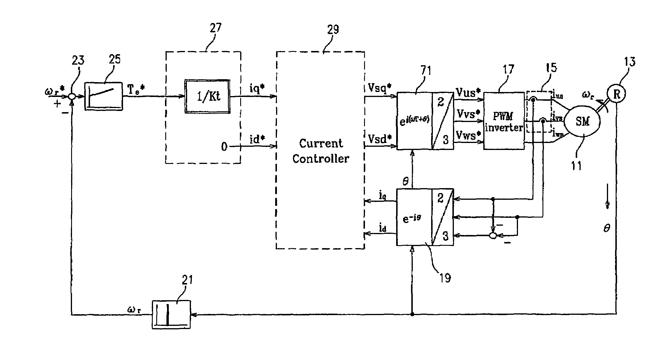
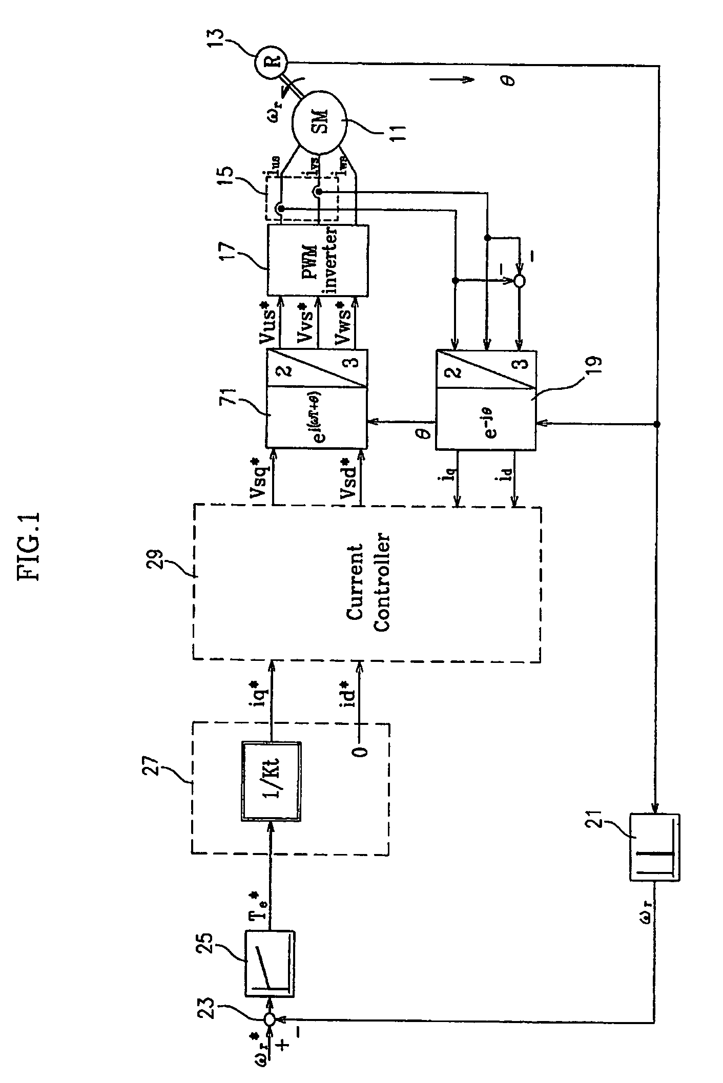
[0018]In FIG. 1, reference numeral 11 denotes a permanent magnet synchronous motor. For example, the permanent magnet synchronous motor 11 may be an Interior Permanent Magnet Synchronous Motor (IPMSM).

[0019]A location detector 13 detects the absolute angular position θ of the rotor of the permanent magnet synchronous motor 11. The absolute angular position θ refers to an angular position where a positive d-axis current is applied to the permanent magnet synchronous motor 11. Note that the absolute angular position and the calculation of the absolute angular position are apparent to those skilled in the art and detailed descriptions thereof are therefore omitted. In some embodiments, the position detector 13 may be a resolver. Hereinafter, reference numeral 13 denotes the resolver.

[0020]A current detector 15 detects drive currents ius, ivs and iws which are applied to the permanen...


PUM


Abstract

A system for controlling a permanent magnet synchronous motor calculates fundamental a d-axis (or q-axis) voltage command based on a difference between a d-axis (or q-axis) current command and a d-axis (or q-axis) current feedback signal, calculates a harmonic suppression d-axis (or q-axis) voltage command used to suppress at least one higher-order harmonic current component included in a harmonic current component which is calculated based on the differences between the current feedback signals and the current commands, and calculates a d-axis (or q-axis) voltage command by adding the fundamental d-axis (or q-axis) voltage command and the harmonic suppression d-axis (or q-axis) voltage command. The d-axis and q-axis voltage commands are transformed into three-phase voltage commands, which are converted into a drive voltage for driving the permanent magnet synchronous motor. As a result, the harmonic current components are significantly suppressed and the motor's overall performance is improved.

Description

CROSS-REFERENCE TO RELATED APPLICATIONS[0001]The present application is based on, and claims priority from, Korean Application Serial Number 10-2004-0108864, filed on Dec. 20, 2004 the disclosure of which is hereby incorporated by reference herein in its entirety.FIELD OF THE INVENTION[0002]The present invention relates to a system and method for controlling the current of a Permanent Magnet Synchronous Motor (PMSM).BACKGROUND OF THE INVENTION[0003]A permanent magnet synchronous motor is a high-power and high-efficiency motor and it is widely used in the industry for hybrid electric vehicles and the like. The motor's high power and high efficiency at least in part rely on the fact that the permanent magnet synchronous motor has no winding in the rotor thereof and a concentric winding in the stator thereof.[0004]However, there is a significant disadvantage associated with the use of concentric windings. In particular, the concentrated winding causes harmonic current components in a b...

Claims


Application Information

Patent Timeline
Patent Type & Authority Patents(United States)
IPC IPC(8): H02P1/46H02P21/00H02P21/22H02P23/16H02P27/04
CPCH02P21/06H02P21/00
Inventor IHM, HYUNG-BINKANG, GU-BAE
Owner HYUNDAI MOTOR CO LTD
Why Eureka
Try Eureka