Method for implementation of a magnetic resonance examination of a patient

a technology for magnetic resonance examination and patient, applied in the direction of magnetic variable regulation, using reradiation, instruments, etc., can solve the problems of invalid acquisition value, inability to plan measurement over the entire patient region, and small scanner, so as to achieve shortened measurement time, improved image quality, and improved resolution

Inactive Publication Date: 2006-12-05
SIEMENS HEALTHCARE GMBH
View PDF7 Cites 30 Cited by
  • Summary
  • Abstract
  • Description
  • Claims
  • Application Information

AI Technical Summary

Benefits of technology

[0013]An advantage of the invention is that the necessary information is acquired continuously over the examination region in a simple manner. In order to achieve this with the method known from German OS 101 50 138, for example, a whole-body scan over 2 meters would have to be implemented in intervals of, for example, 3 cm measurements of approximately 10 s measurement duration each. This can be implemented in 0.5 to 20 min in accordance with the invention with a measurement with continuous table movement. This time gain allows a higher resolution in the table shift direction, since in principle each table position can be evaluated. The piecing together of axial measurement regions and the errors associated with this procedure are omitted. Furthermore, an advantage is that the spatial resolution can be individually adapted to the various items of partial information. Thus, for example, the transmitter reference amplitude can be doubled as often as the shim parameters are acquired.
[0014]A further advantage is that parameters can be determined from M continuously measured data sets of a measurement N>M (in contrast to a stationary measurement in which only the current parameter of interest is measured). Furthermore, the measurements at different locations (i.e. patient bed moved in to different lengths) can be related to one another, for example in order to smooth (average) the curve of measurement values in the z-direction (i.e. the shift direction of the patient bed) to compensate measurement imprecisions of each individual measurement or to make a “prediction” of a new measurement value range from data already acquired.
[0015]Another advantage of the invention is that information is determined in the framework of the low-resolution calibration measurement, which information can be used to automate steps that were previously manually implemented, such as, for example, parts of the patient registration, the measurement preparation and / or the measurement itself. The measurement time is thereby shortened overall and the image quality is increased. The time invested in the calibration measurement thus subsequently leads to a time saving and an effective implementation of the magnetic resonance examination.
[0016]In an embodiment, a third group of measurement protocol parameters is calculated from the patient information and the technical information. For example, this enables the use of a position-dependent patient-related SAR prediction in the measurement protocol creation and SAR monitoring in the later measurement (SAR: specific absorption rate). An exact, SAR determined with positional dependence enables the optimal radiation of radio frequency magnetic fields. In the case of a shift of different regions of the patient through the acquisition region, this exact SAR measured on the body is absolutely necessary in order to not have to conservatively irradiate, whereby the signal and therewith the contrast would decrease.
[0017]The method according to the invention refers to a non-local patient examination in which the examination region to be examined is larger than the acquisition region (given by the region of highest homogeneity (isocenter) of the magnet). The term “larger” as used herein encompasses the situation in which the examination region has sub-regions, which do not necessarily have to be connected with one another and of which one or more are smaller than the acquisition region, but that cannot be acquired together with one local measurement. Since technical parameters of the magnetic resonance apparatus as well as patient information necessary for measurement planning change dependent on the position of the patient bed and the position of the patient relative to the acquisition volume, a measurement (data acquisition) planning only with regard to the acquisition region is not sufficient to adjust an optimal imaging for the larger examination volume to be imaged. As used herein “technical parameters” of the magnetic resonance apparatus are, for example, the basic magnetic field homogeneity, possible shim parameters, the center frequency of the radio frequency magnetic field, and the transmission and reception power of the radio frequency magnetic field. As used herein “patient information” encompasses, among other things, the measurements of the patient (such as length and weight) as well as the position of an organ or body part of interest in relation to the patient bed or in relation to the acquisition volume.
[0018]In accordance with the invention an optimally fast calibration measurement with a low resolution can be implemented one time before the actual high-resolution magnetic resonance examination, and additional patient information, which can be determined only based on the shifting of the patient is acquired in an expansion of the measurements known as pre-scan measurements. This calibration measurement is implemented after a concluded patient positioning which, for example, includes the patient placement and, if applicable, the application of the radio frequency coils, the PMU units and / or placement of possible contrast agent injection needles.

Problems solved by technology

A problem occurs in the examination of larger body regions, such as the entire patient or non-contiguous regions thereof, because the acquisition volume in the MR scanner becomes smaller as the gradient field system becomes shorter.
Measurement planning over the entire patient region thus is not possible.
A disadvantage of this method is that the acquired valued is valid only for a specific table position.

Method used


Image

  • Method for implementation of a magnetic resonance examination of a patient
  • Method for implementation of a magnetic resonance examination of a patient
  • Method for implementation of a magnetic resonance examination of a patient

Examples


Embodiment Construction

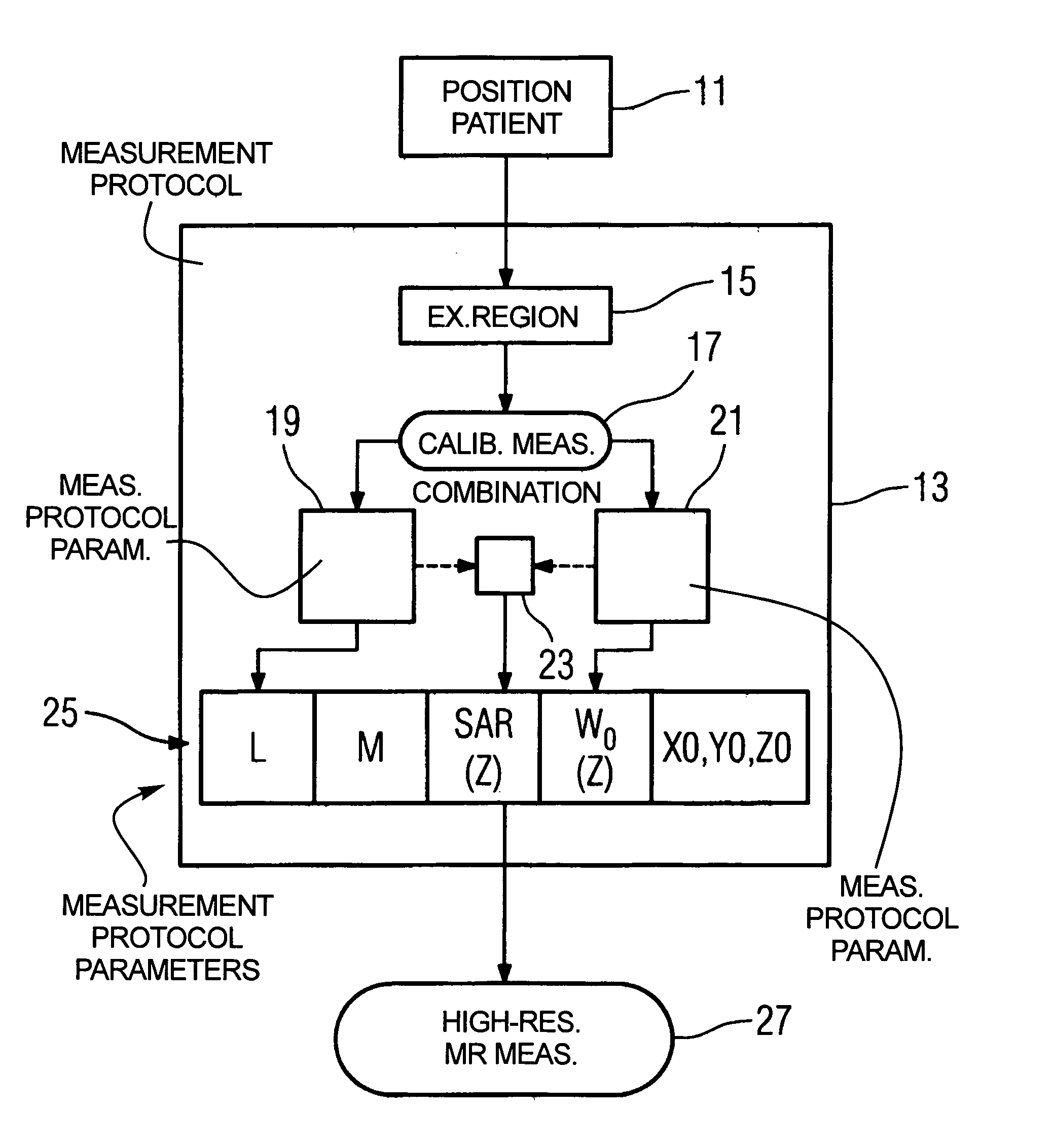
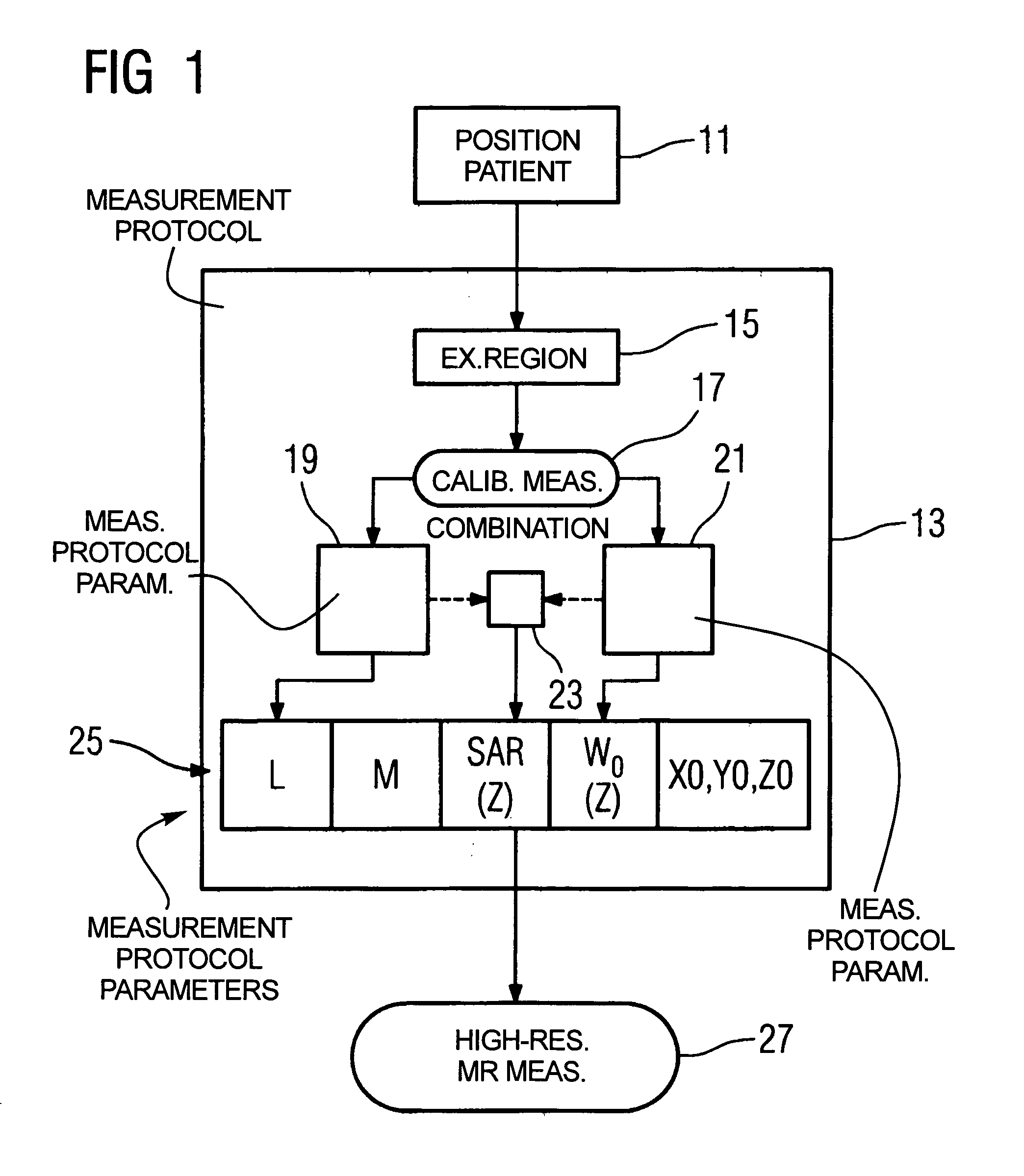
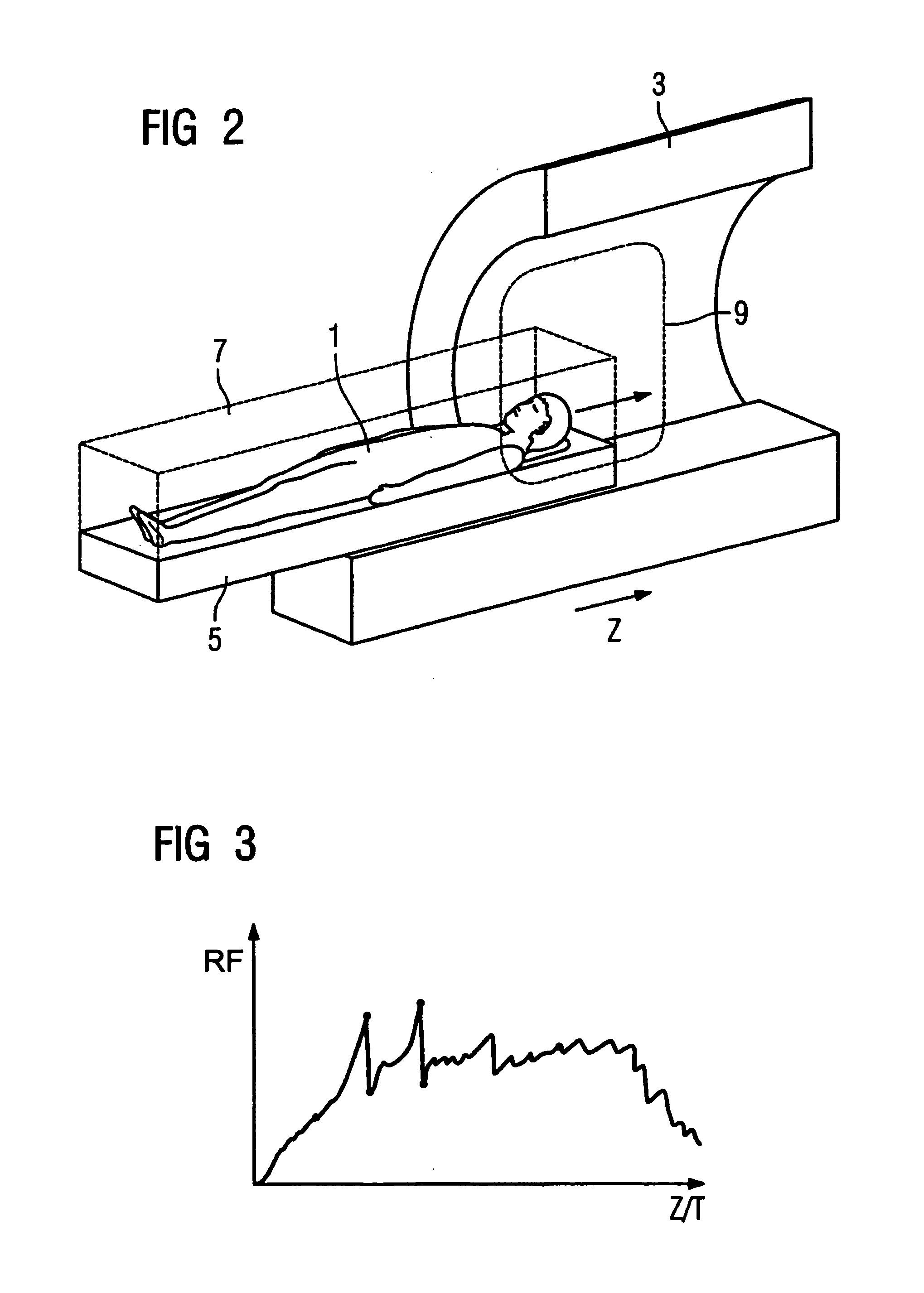
[0034]FIG. 1 shows a flowchart of an exemplary embodiment of the method according to the invention. FIG. 2 shows an apparatus to implement the method. A patient 1 is to be “non-locally” examined with a magnetic resonance apparatus 3 that has a movable patient bed 5. “Non-locally” thereby means that an examination volume 7 is larger than an acquisition volume 9 of the magnetic resonance apparatus 3. The patient 1 on the patient bed 5 is moved in the z-direction (i.e. in the axial direction) through the acquisition volume 9 of the magnetic resonance apparatus 3 for acquisition of data from the entire examination volume 7.

[0035]The examination of the patient 1 ensues as follows. First, a positioning 11 of the patient 1 on the patient bed 5 occurs. As needed, local radio frequency coils may also positioned on the body of the patient 1. A measurement protocol 13 is subsequently created, wherein an establishment 15 of the examination region 7 ensues. For example, “whole body” could be set...


PUM


Abstract

In a method for implementation of a magnetic resonance examination of a patient with an imaging medical magnetic resonance apparatus with a movable patient bed, for of an examination volume of the patient that is larger than an acquisition volume of the magnetic resonance apparatus, anatomical patient information and second technical information for setting the magnetic resonance apparatus are acquired dependent on the position of the patient bed from magnetic resonance signals acquired in a low-resolution calibration measurement (scan). A first group of measurement protocol parameters is generated from the patient information and a second group of measurement protocol parameters is generated from the technical information, to generate a measurement protocol for a subsequent high-resolution magnetic resonance examination.

Description

BACKGROUND OF THE INVENTION[0001]1. Field of the Invention[0002]The present invention concerns a method for implementation of a magnetic resonance examination of a patient with an imaging medical magnetic resonance apparatus with a movable patient bed, wherein an examination volume of the patient to be examined is larger than the acquisition volume of the magnetic resonance apparatus.[0003]2. Description of the Prior Art[0004]A goal of magnetic resonance tomography and magnetic resonance spectroscopy is to implement patient examinations that are ever shorter and are conducted with stronger gradient magnetic fields that are produced with shorter gradient field systems (coils). A problem occurs in the examination of larger body regions, such as the entire patient or non-contiguous regions thereof, because the acquisition volume in the MR scanner becomes smaller as the gradient field system becomes shorter. The magnetic resonance apparatuses (MR scanners) that are advantageous with reg...

Claims


Application Information

Patent Timeline
Patent Type & Authority Patents(United States)
IPC IPC(8): G01V3/00A61B5/055G01R33/28G01R33/563G01R33/58
CPCG01R33/56375G01R33/58
Inventor CAMPAGNA, SWENHARDER, MARTINHEUBES, PETERKAIM, RAINERKANNENGIESSER, STEPHANKIEFER, BERTHOLDMOHR, CECILEWOHLFARTH, KATRIN
Owner SIEMENS HEALTHCARE GMBH
Why Eureka
Try Eureka