Contactor assembly for a circuit breaker

a circuit breaker and contactor technology, applied in the field of circuit breaker, can solve the problems of severe damage to the circuit breaker and the load device, and the inability to obtain instant current limiting characteristics, and achieve the effect of fast performing a current limiting function

Active Publication Date: 2006-12-05
LS IND SYETEMS CO LTD
View PDF4 Cites 17 Cited by
  • Summary
  • Abstract
  • Description
  • Claims
  • Application Information

AI Technical Summary

Benefits of technology

[0015]Therefore, an object of the present invention is to provide a contactor assembly for a circuit breaker capable of preventing a movable contactor from generating a fluctuation at a center thereof when the movable contactor rotates without a rotation axis, capable of fast performing a current limiting function, capable of preventing the movable contactor separated from a fixed contactor from returning to a contact state to the fixed contactor for a predetermined time, and capable of facilitating an assembly thereof.
[0016]To achieve these and other advantages and in accordance with the purpose of the present invention, as embodied and broadly described herein, there is provided a contactor assembly for a circuit breaker comprising: a U-shaped first fixed contactor connected to a power source on a circuit; a U-shaped second fixed contactor connected to an electric load on the circuit; a movable contactor having contacts at both ends thereof, the contacts respectively corresponding to the first fixed contactor and the second fixed contactor, and movable to a contacted position to the first and second fixed contactors or a separated position from the first and second fixed contactors; a shaft provided with an opening for allowing independent rotating of the movable contactor by an electromagnetic repulsive force between the movable contactor and the first and second fixed contactors, for rotatably supporting the movable contactor; a pair of first spring supporting pins symmetrically fixed on both lateral surfaces of the movable contactor; a cam plate positioned between the movable contactor and the shaft, fixed to the shaft, and having an outer circumferential surface formed as a cam surface composed of a plurality of arc surfaces having different centers and radiuses, wherein the cam surface includes a first cam surface having an arc center positioned at an inner side of the outer circumferential surface, a second cam surface having an arc center positioned at an outer side of the outer circumferential surface, and a third cam surface disposed between the first cam surface and the second cam surface, the third cam surface having an arc center positioned at an inner side of the outer circumferential surface; a pair of symmetric second spring supporting pins contacting the first cam surface of the cam plate when the movable contactor is in contact with the first and second fixed contactors, and rotated along the movable contactor being rotated when an electromagnetic repulsive force is generated between the movable contactor and the first and second fixed contactors thereby to be slid on the third cam surface from the first cam surface of the cam plate and thus to be in contact with the second cam surface for a predetermined time, for preventing the movable contactor from returning towards the first and second fixed contactors; a link for connecting the first spring supporting pins to the second spring supporting pins; and a spring having one end supported by the first spring supporting pins and the other end supported by the second spring supporting pins, for providing an elastic force so that a contact pressure between the movable contactor and the fixed contactors can be maintained under a state that the movable contactor is in contact with the first and second fixed contactors, and for providing an elastic force in a direction to accelerate a separation of the movable contactor from the first and second fixed contactors when the second spring supporting pins are slid on the third cam surface as an electromagnetic repulsive force is generated between the movable contactor and the first and second fixed contactors.

Problems solved by technology

Accordingly, an instant current limiting characteristic is not obtained and severe damages may be caused to the circuit breaker and the load devices.

Method used


Image

  • Contactor assembly for a circuit breaker
  • Contactor assembly for a circuit breaker
  • Contactor assembly for a circuit breaker

Examples


Embodiment Construction

[0032]Reference will now be made in detail to the preferred embodiments of the present invention, examples of which are illustrated in the accompanying drawings.

[0033]Hereinafter, a contactor assembly for a circuit breaker according to the present invention will be explained in more detail with reference to the attached drawings.

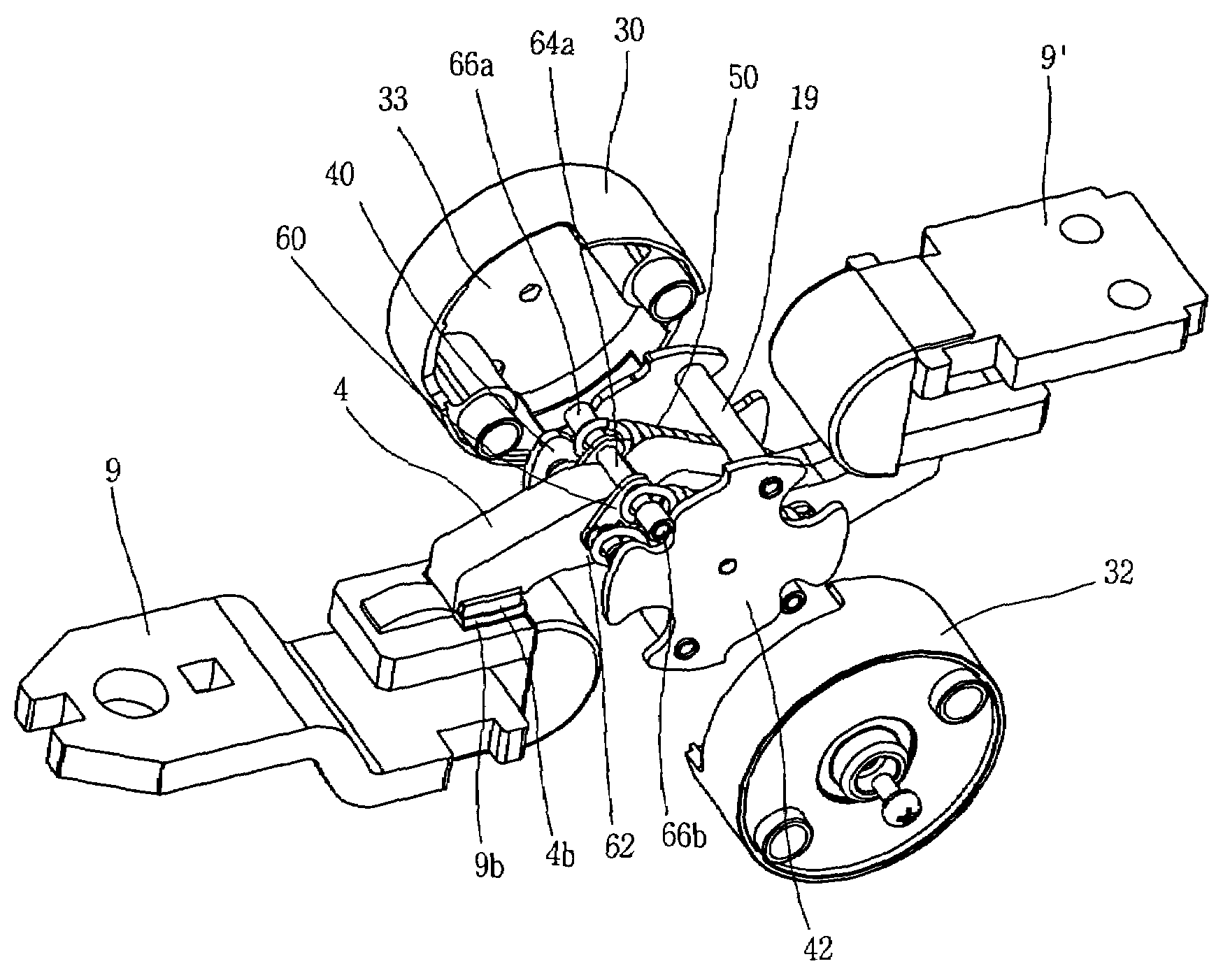
[0034]FIG. 4 is a cut-perspective view showing an inner construction of a single pole switching unit for a circuit breaker to which a contactor assembly for a circuit breaker according to the present invention has been applied. As shown in FIG. 4, the contactor assembly for a circuit breaker according to the present invention can be embodied to a circuit breaker that a contactor assembly and an extinguishing mechanism provided according to each phase (in other words “each pole”) are received in a mold case formed of an insulating material as a unit. The contactor assembly for a circuit breaker according to the present invention comprises a U-shaped (so calle...


PUM


Abstract

A contactor assembly for a circuit breaker comprises a first spring supporting pin, a cam plate, a second spring supporting plate, a link, and a spring. When a movable contactor is rotated without a rotation axis, a fluctuation of a rotation center of the movable contactor is not generated and a current limiting function is fast performed. Also, after contacts are separated from each other, the movable contactor is prevented from returning towards fixed contactors and the separated position is maintained for a predetermined time. An assembly process of the contactor assembly is simplified.

Description

BACKGROUND OF THE INVENTION[0001]1. Field of the Invention[0002]The present invention relates to a circuit breaker for protecting an electric circuit and electric load equipments by automatically breaking the circuit at the time of occurrence of an overload or a short circuit, and more particularly, to a contactor assembly for such a circuit breaker.[0003]2. Description of the Background Art[0004]A mold cased circuit breaker (MCCB) is installed at an electric power distributing board among several electric power systems of a factory and a building. The circuit breaker serves as a switch for supplying or cutting off electric power source to a load side under no load state, and cuts off power supplied to a load side from a power side in order to protect a circuit and electric load equipments when a great abnormal current due to a short-circuit or a ground fault flows on a circuit under a load state.[0005]FIG. 1 is a sectional view showing an inner construction of a circuit breaker in ...

Claims


Application Information

Patent Timeline
Patent Type & Authority Patents(United States)
IPC IPC(8): H01H75/00
CPCH01H1/205H01H77/104H01H1/2058H01H73/04H01H75/00H01H71/10
Inventor KIM, YONG-GI
Owner LS IND SYETEMS CO LTD
Why Eureka
Try Eureka