
Wireless internal antenna for home network and digital electric home appliance

a digital electric home appliance and home network technology, applied in the direction of resonant antennas, substantially flat resonant elements, wireless communication, etc., can solve the problems of affecting the service life the disfigurement of the home network, and the fragility of the conventional wireless antenna during transportation or movement, so as to prevent the breakage

Inactive Publication Date: 2006-12-05
LG ELECTRONICS INC
View PDF8 Cites 13 Cited by
  • Summary
  • Abstract
  • Description
  • Claims
  • Application Information

AI Technical Summary

Benefits of technology

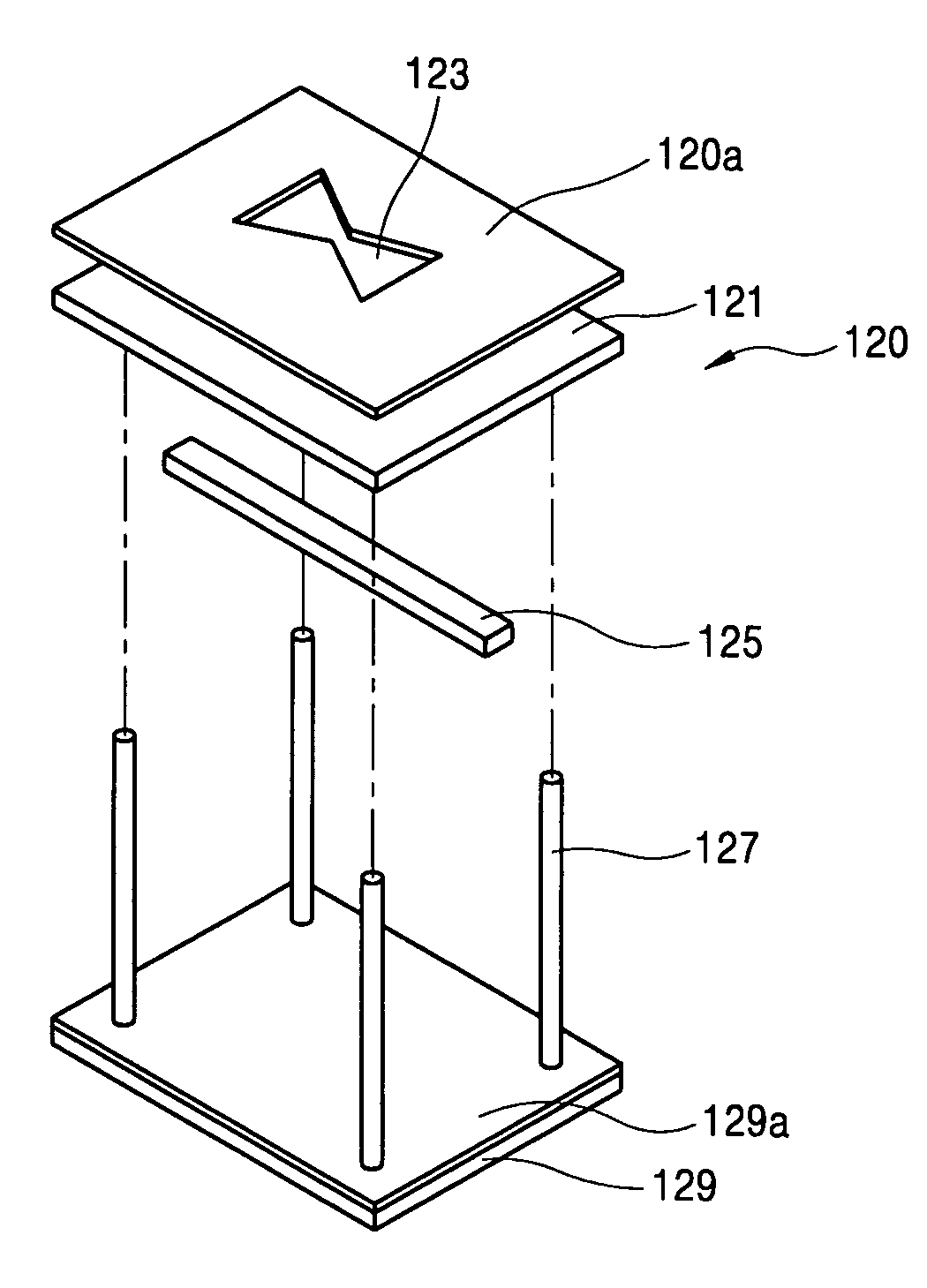
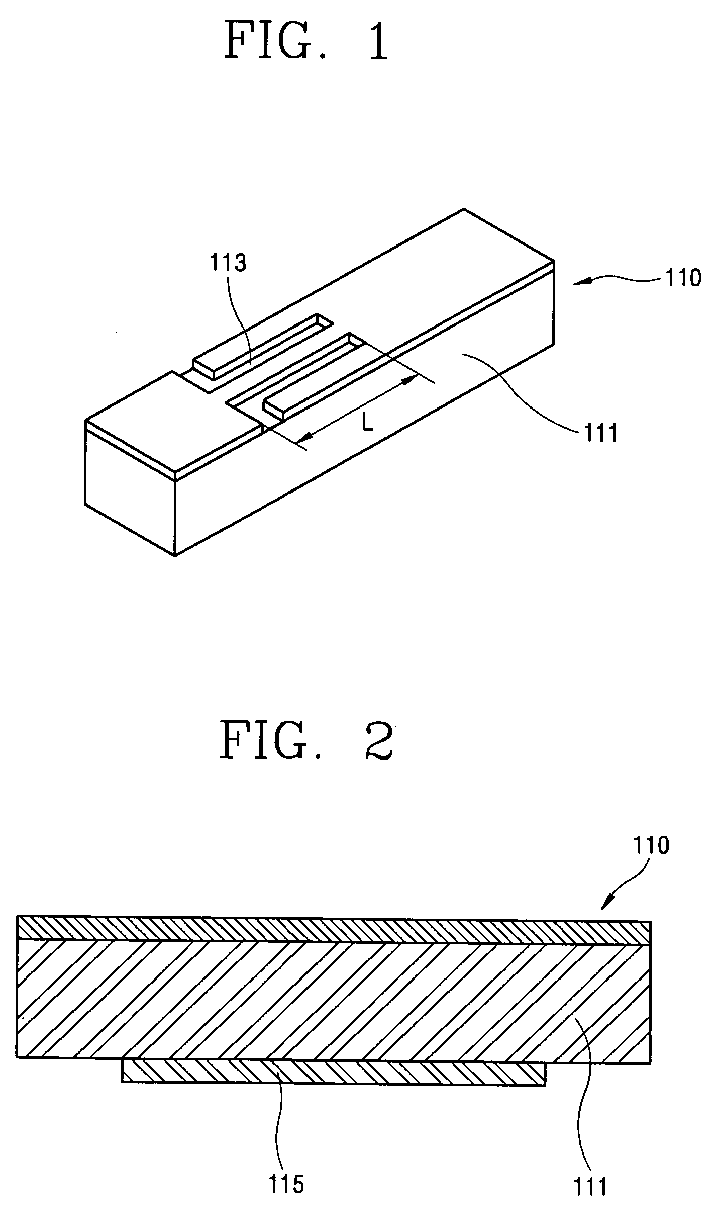
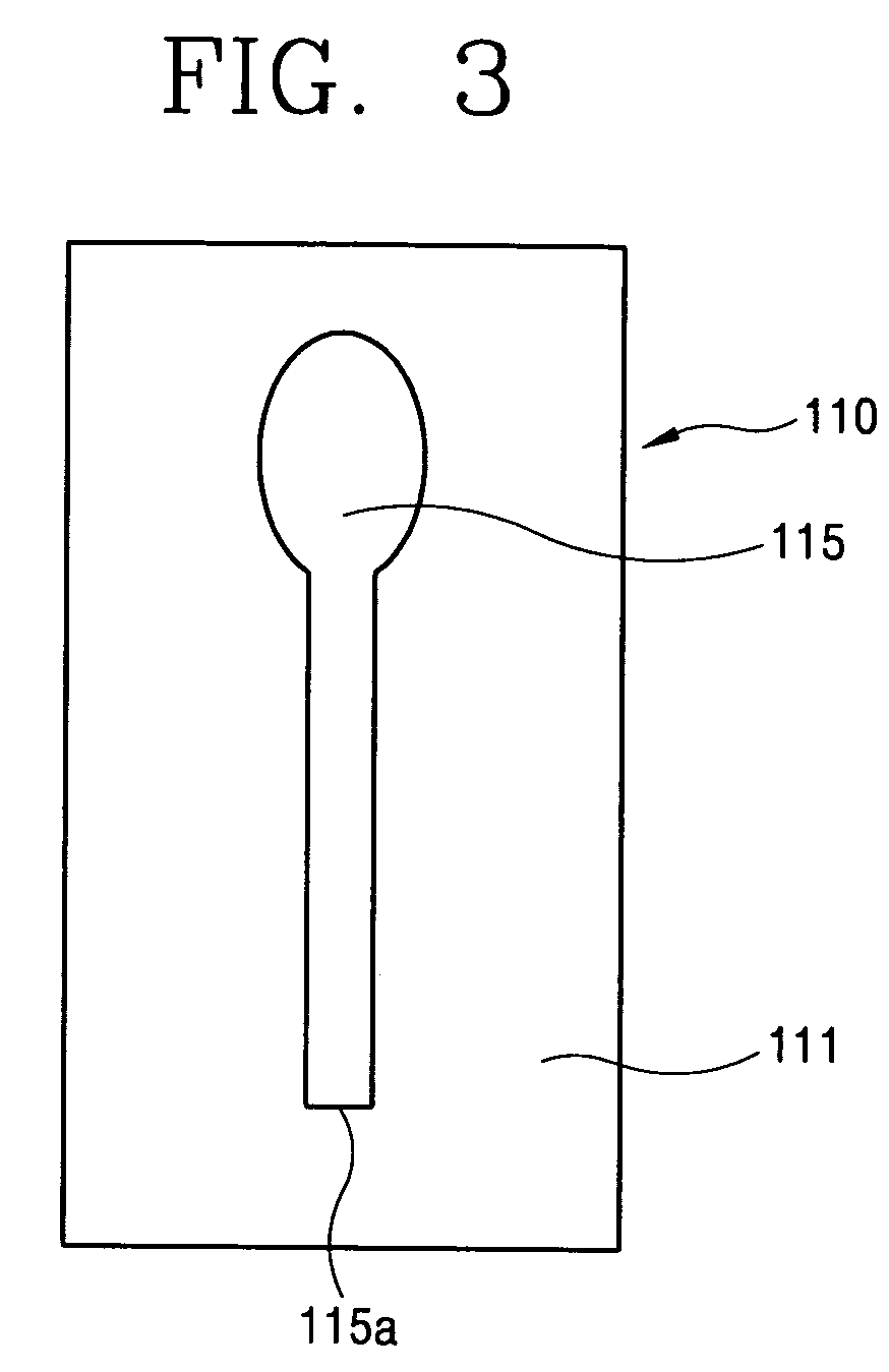
The present invention provides a wireless internal antenna for a home network and digital electric home appliance that can protect the appearance of the server and client and prevent damage. The antenna has superior characteristics in both the 2.4 GHz and 5 GHz bands. The antenna includes a wireless antenna for the client and a wireless antenna for the server. The client antenna has a tuning slot and a patch pole, while the server antenna has an air slot and a feeding line. The server antenna can be placed horizontally and is supported by a supporting portion. The wireless antennas have different emission patterns, with the client antenna having a non-directional pattern and the server antenna having a directional pattern.

Problems solved by technology

The conventional wireless antenna by nature is difficult to be miniaturized due to its sensitivity with respect to frequency variation according to circumferential environments.
However, this external wireless antenna is mounted on the outside of each server and client, which results in its disfigurement and its fragility during transportation or movement.
As a result of this, because the antenna can not perform an impedance matching, its receive sensitivity is degraded and even reception can be impossible thereby.

Method used


Image

  • Wireless internal antenna for home network and digital electric home appliance
  • Wireless internal antenna for home network and digital electric home appliance
  • Wireless internal antenna for home network and digital electric home appliance

Examples


Embodiment Construction

[0039]Reference will now be made in detail to the preferred embodiments of the present invention, examples of which are illustrated in the accompanying drawings.

[0040]Hereinafter, it will be explained of a wireless internal antenna for a home network and digital electric home appliance in accordance with the present invention with reference to the attached drawings.

[0041]As can be seen from FIGS. 1 to 6, the wireless internal antenna for the home network and digital electric home appliance includes: a wireless antenna for a client 110 having a tuning slot 113 at an upper surface of a client device 111 to realize an impedance matching at a first communication band (e.g., the band of IEEE802.11b (a band of 2.4 GHz)) and having a certain type patch pole 115 at a lower surface of the client device 111 to have return characteristics at a second communication band (e.g., the band of IEEE802.11a (a band of 5 GHz)); and a wireless antenna for a server 120, enabling transmission / reception to...


PUM


Abstract

Disclosed is a wireless internal antenna for a home network and digital electric home appliance which comprises: a wireless antenna for a client having a tuning slot at an upper surface of a client device to realize an impedance matching at a band of IEEE802.11b (a band of 2.4 GHz) and having a certain type patch pole at a lower surface of the client device to have return characteristics at a band of IEEE802.11a (a band of 5 GHz); and a wireless antenna for a server, enabling transmission / reception to / from the client device, having an air slot at an upper surface of a server device and a feeding line at a lower surface thereof, and the server device is supported at a ground plate by a supporting portion installed at a lower part thereof.

Description

BACKGROUND OF THE INVENTION[0001]1. Field of the Invention[0002]The present invention relates to a wireless internal antenna for a home network and a digital electric home appliance, and particularly, to a wireless internal antenna for a home network and a digital electric home appliance installed in a server and a client for embodying a home network.[0003]2. Description of the Background Art[0004]Recently, since a wireless network technique improved, an internet digital information home appliance (e.g., a remote control of home electronics, an electronic commercial transaction through an internet, a game, an education, a business, etc) has been improved by accessing to digital products (such as a digital TV, DVD, an internet refrigerator, a computer, a telecommunications equipment, and so on) using a home network.[0005]In general, a home network includes such networks, namely, an information network connecting a PC to peripheral devices, an AV network connecting a PC to a TV receiv...

Claims


Application Information

Patent Timeline
Patent Type & Authority Patents(United States)
IPC IPC(8): H01Q13/10H01Q1/38H01Q1/24H01Q1/22H01Q9/04H01Q9/28H04L12/28
CPCH01Q9/0407H01Q9/285H01Q1/22H01Q1/2258H01Q1/38H04W84/12H01Q1/24
Inventor KO, YOUNG-JOONPARK, JAE-YEONG
Owner LG ELECTRONICS INC
Learn More