Mixed cut gemstone

a technology of mixed cut gemstones and gemstones, which is applied in the field of unique cut design of diamonds, can solve the problems of unobstructed viewing of the pavilion facets of diamonds, and achieve the effects of enabling emphasis and control of optical properties, sufficient surface area, and unique and attractiveness

Inactive Publication Date: 2006-12-12
DIAMOND INNOVATIONS INC
View PDF48 Cites 24 Cited by
  • Summary
  • Abstract
  • Description
  • Claims
  • Application Information

AI Technical Summary

Benefits of technology

[0030]The conventional step cut pavilion has been further modified by the addition of sixteen triangular lower girdle facets to the first step of the pavilion. Each side and corner of the first pavilion step is divided into three triangular facets. These steeply cut triangular lower girdle facets function to successfully combine the step cut pavilion and brilliant crown into a cohesive stone that obeys optical laws, while enabling emphasis and control of the optical properties that make a diamond a prized material. The additional pavilion first step side and corner facets are arranged in visual coordination with the brilliant cut crown so that when viewed through the crown table, the first step facet arrangement does not interfere with the crown facet arrangement, but instead mirrors the crown facet arrangement. In this way, the integrity of the stone is maintained and a cohesive stone results. The top points of the four large crown bezel facets are aligned with the pavilion first step facet junction when viewed through the table so that the width of each side of the crown facet arrangement as measured from table to girdle, mirrors the length of the first step facet arrangement on each pavilion side, as measured from girdle to first step facet junction. The crown facets are further aligned with the added triangular corner and side facets of the first pavilion step so that when viewed through the crown table the first pavilion step facet arrangement roughly mirrors the arrangement of the crown facets. This alignment creates visual connection points between the crown and the pavilion of the stone when viewed through the table and further prevents interference between the crown and pavilion facets that would affect the brilliance of the stone and the view into the stone. The alignment further creates a mirroring effect between: the small bezel facets of the crown and the pavilion main corner first step facets, the crown upper girdle facets and the pavilion corner side first step facets and the large crown bezel facets and the pavilion side main first step facets. As a result of the alignment of these facets, the table frames a clean and uninterrupted view of the concentric second and third step facet junctions of the pavilion that work down to the culet without interference of crown or first pavilion step facets when the stone is viewed from above. Two triangular facets added to each pavilion corner create the rounded square shape of the pavilion. The rounded pavilion corners do not create 90° angles.
[0031]Moreover, the traditional step cut pavilion has been modified by a deeply cut first pavilion step. This first step makes up one-third of the total pavilion depth. The succeeding second, third and fourth pavilion steps are cut of equal depth and make up the remaining two-thirds of the pavilion depth. The deepness of the elongated first step, cut at high angles relative to said girdle plane, creates a first step that is closer to perpendicular in relation to the table than a conventionally step cut pavilion, thus allowing the succeeding three steps to be worked within the critical angle of the stone. This deeper first step is necessary to prevent the pavilion facets from interfering by crossing with the facets of the brilliant cut crown when the stone is viewed from above. The top points of the crown main bezel facets, adjacent to the table, are aligned with the facet junctions between the first and second step on the pavilion. This alignment becomes a visual and functional connection point between the crown and the pavilion of the diamond. Thus, the deeply cut first step allows a view the succeeding second, third and fourth steps of the pavilion that create the architecture of the stone viewed from above. In a typical step-cut stone the succeeding pavilion facet lines are concealed from view by the facet lines of the first step. The ability to look into the stone to view the facet junctions of the succeeding steps allows a viewer a depth perception not available with conventional brilliant or step cut stones.
[0032]In the present invention, the crown angle is cut so as to give sufficient surface area for dispersion and reflection. The first step has been designed to create a visual and cohesive connection between the facet points of the crown and the first step. The deep first step emphasizes contrast in the open steps below and the fire of the brilliant cut crown. This combination of facet shapes, quantity of facets, facet angles, facet lines that are visible when looking through the top of the stone together with the rounded square shape of the girdle and pavilion creates a unique and attractive design with a unique function that does not currently exist in the marketplace.
[0033]Stone cuts vary in popularity, and hence in value. The market advantage to this invention is the creation of a unique stone that is immediately recognizable to both the consumer and the professional. This invention contemplates a significant change to existing diamond designs that goes beyond the addition of new facets. By altering, controlling and yet preserving the brilliance and fire of a diamond, the present invention allows the viewer to explore the facets deep in the pavilion of the stone, creating a unique viewing experience. The stone of the present invention commands a thoughtful look from the viewer by first attracting attention and then drawing that attention deeper into the heart of the gemstone.

Problems solved by technology

Unobstructed viewing of the pavilion facets of a diamond is not possible with traditional brilliant cuts because the view of the pavilion is obscured by light reflected by the maximized brilliance of the crown facets.

Method used


Image

  • Mixed cut gemstone
  • Mixed cut gemstone
  • Mixed cut gemstone

Examples


Embodiment Construction

[0034]In describing a preferred embodiment of the invention illustrated in the drawings, specific terminology will be employed for clarification. However, the invention is not intended to be limited to the specific terms selected, and each specific term includes all technical equivalents, which operate in a similar manner to accomplish a similar purpose.

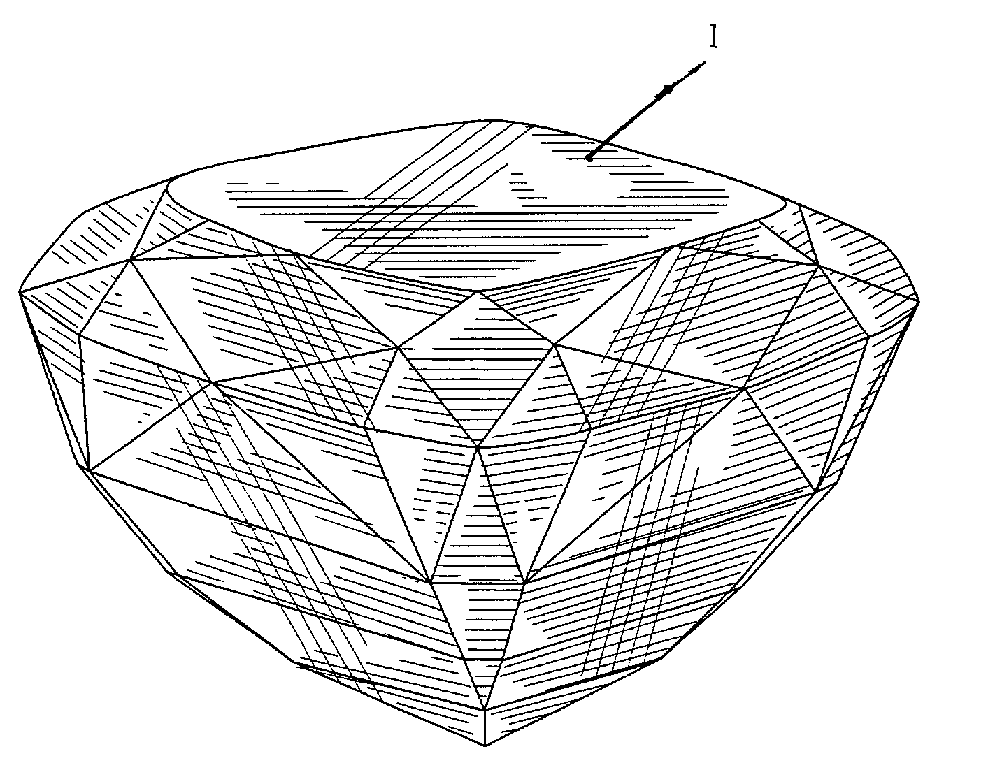
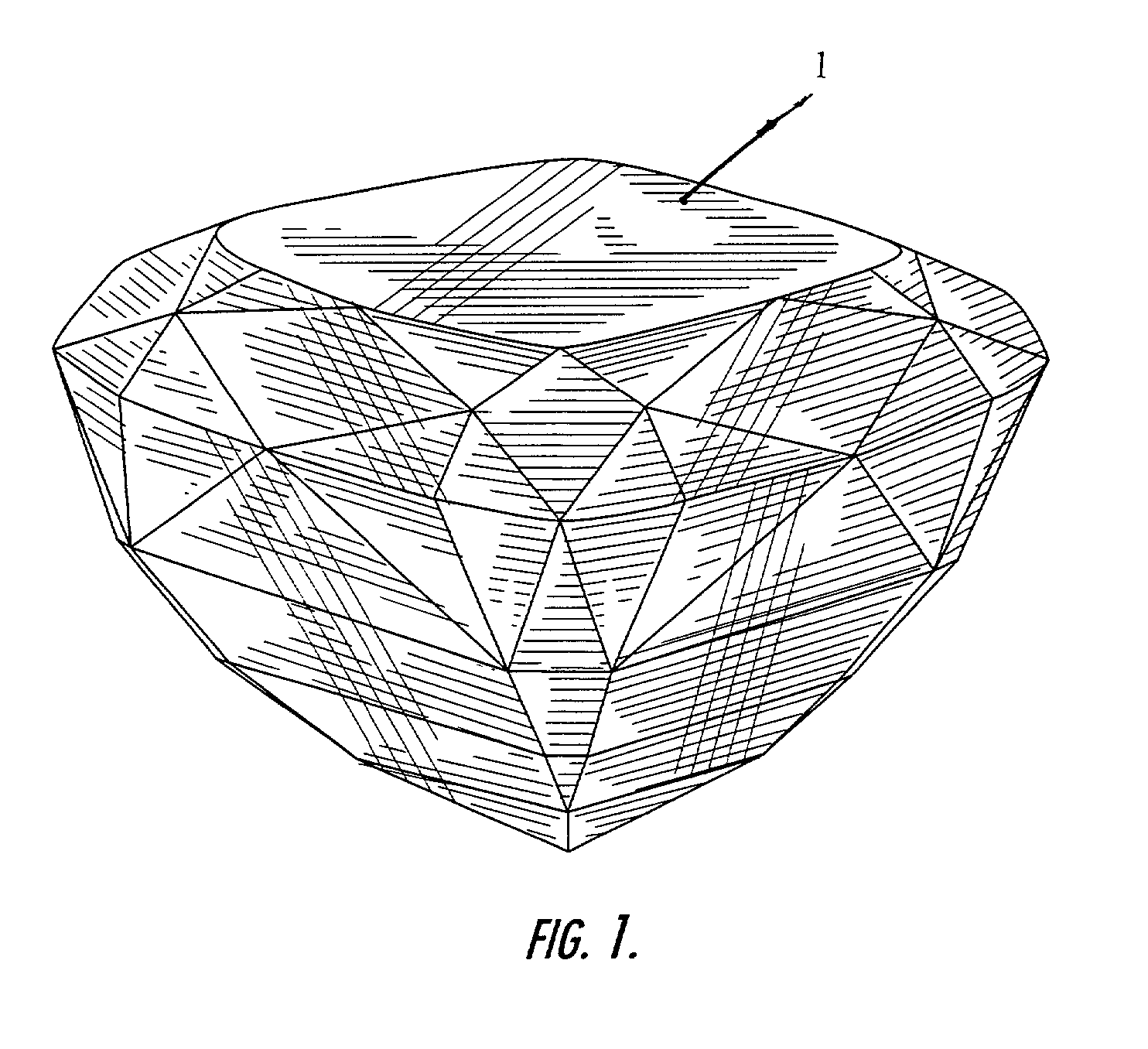
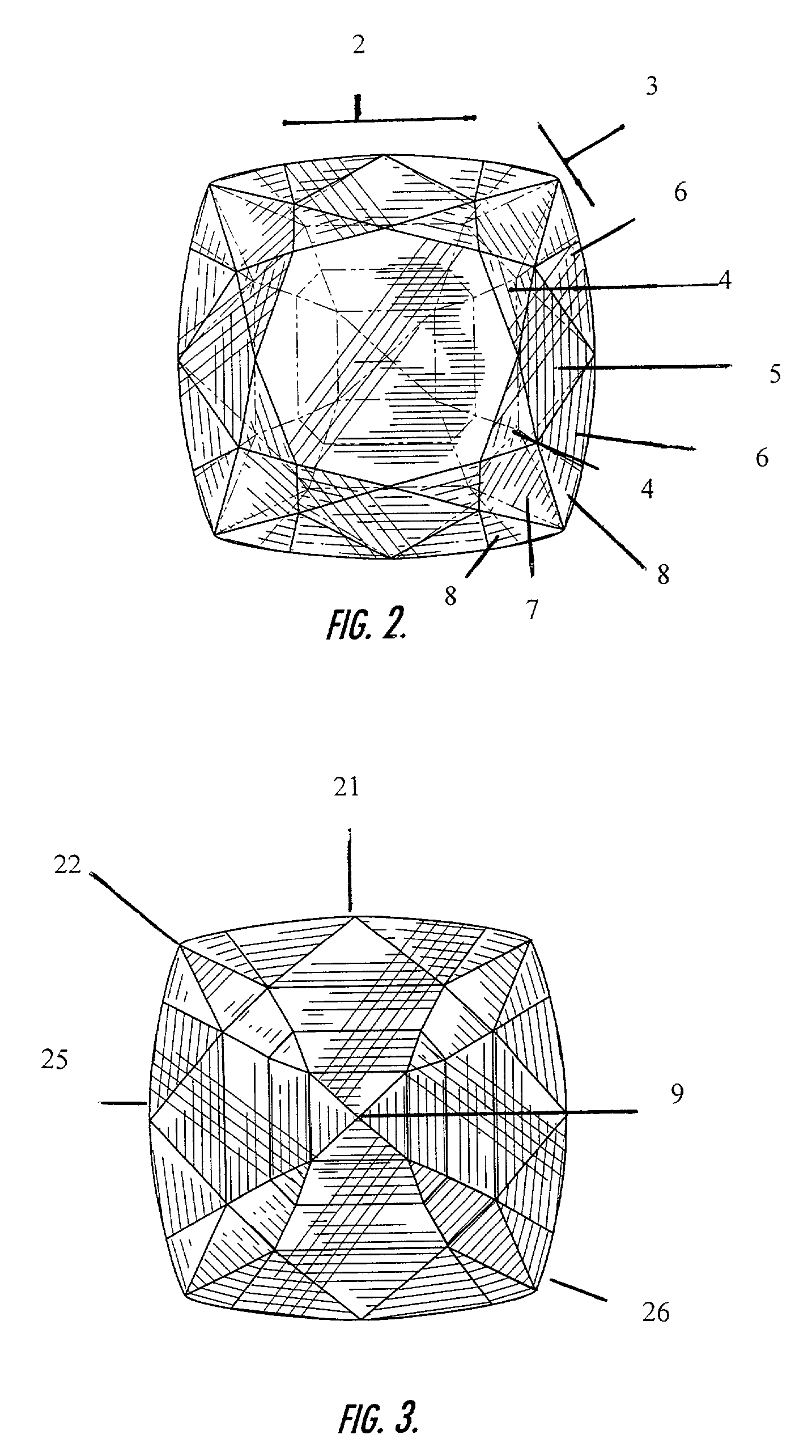
[0035]In one embodiment of this invention, a mixed-cut gemstone is provided comprising a brilliant cut crown and a modified step cut pavilion. This mixed cut gemstone comprises a girdle, a brilliant cut crown above said girdle, a modified step cut pavilion below said girdle and a culet. The modified step cut pavilion comprises at least two steps, a first step 14 descending from the girdle 10 to the first step facet junction 11 and a second step 15 descending from the first step facet junction to the culet 18. In the preferred embodiment of this invention four pavilion steps are provided.

[0036]Ranges for the angles formed by each crow...


PUM


Abstract

A mixed cut gemstone comprising a girdle, a crown above the girdle and a pavilion below the girdle. The crown has a girdle break, a table break and a table. The table break is cut with triangular shaped facets and the girdle break is cut with triangular and quadrilaterally shaped facets. The present invention also describes a pavilion having a width and a length formed by two pairs of opposing pavilion sides and four pavilion corners. The pavilion is composed of four steps including: a first step descending from said girdle to a first step facet junction, a second step descending from said first step facet junction to a second step facet junction, a third step descending from said second step facet junction to a third step facet junction, and a fourth step descending from said third step facet junction to said culet. This mixed cut gemstone enables the appreciation of the desirable characteristics of a diamond in ways that prior art cuts do not allow.

Description

[0001]The applicant wishes to claim priority from Provisional Application Filling No. 60 / 292,243 filed in the USPTO on May 18, 2001.BACKGROUND OF THE INVENTION[0002]The present invention pertains to gemstones and, more particularly, to a unique cut design for a diamond featuring controlled brilliance and dispersion that is immediately and recognizably different from cut designs currently known in the art in that it allows a viewer to readily perceive and appreciate the depth of the diamond material.[0003]Diamond is an extremely hard substance that is created over millions of years in the depths of the earth under extremely harsh conditions. Extremely rare and difficult to secure, diamonds are desirable to consumers because of the unique and attractive distinguishing properties of cut stones including: brilliance, dispersion and scintillation. This combination of optical properties is unique to diamond material and is maximized when a diamond is well cut. The facet arrangement of a c...

Claims


Application Information

Patent Timeline
Patent Type & Authority Patents(United States)
IPC IPC(8): A44C17/00B44F3/00A44C27/00
CPCA44C17/001
Inventor MARDKHA, JOSEPH
Owner DIAMOND INNOVATIONS INC
Why Eureka
Try Eureka